

Elevating gear of water closet
A technology for lifting devices and toilets, applied in water supply devices, flushing toilets, buildings, etc., can solve the problems of difficulty in taking care of young children, complex structure of jack lifting lever mechanism, high cost, etc., and achieves easy maintenance, wide range of applicable people, low cost effect
- Summary
- Abstract
- Description
- Claims
- Application Information
AI Technical Summary
Problems solved by technology
Method used
Image

Examples
Embodiment 1
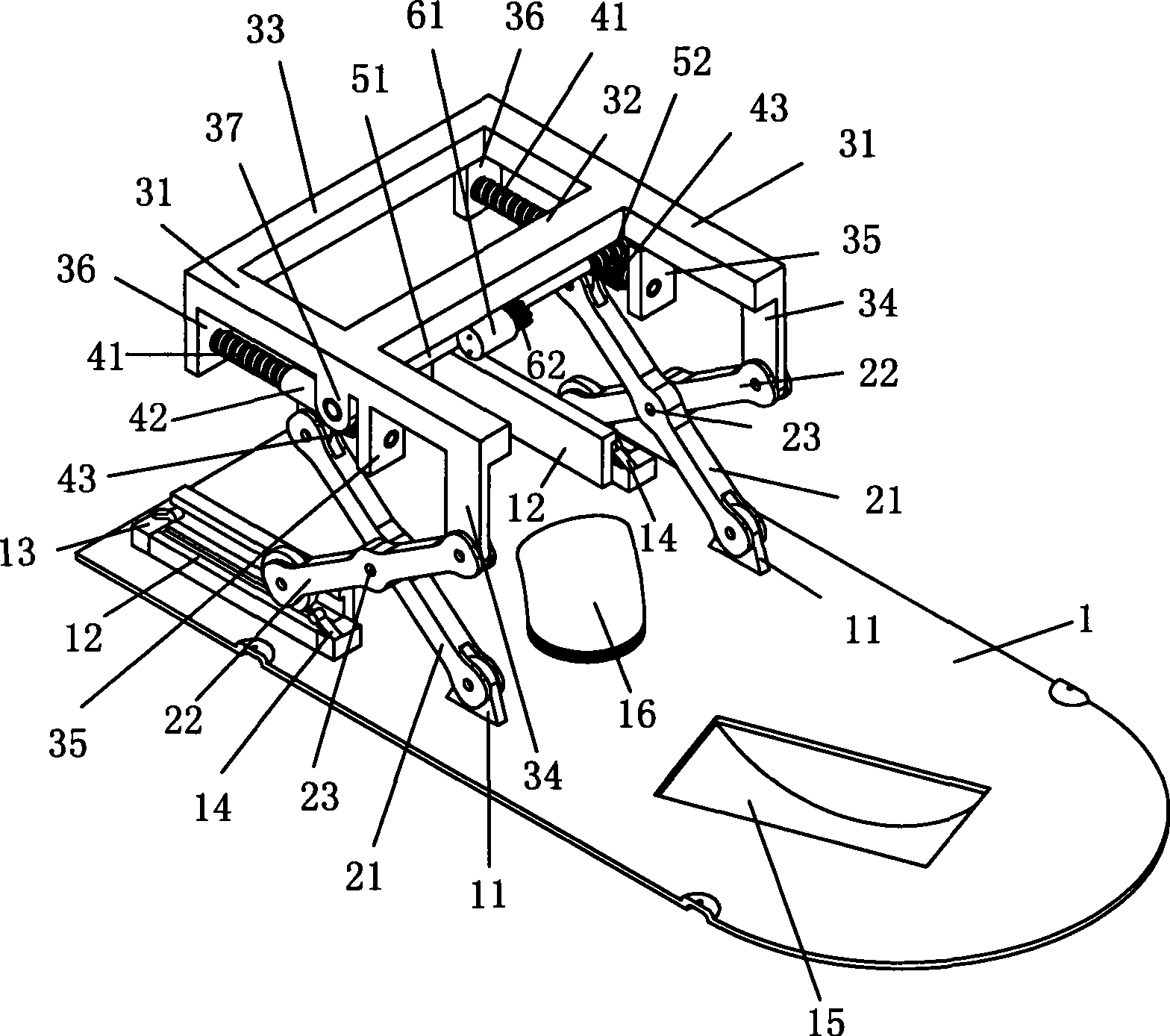
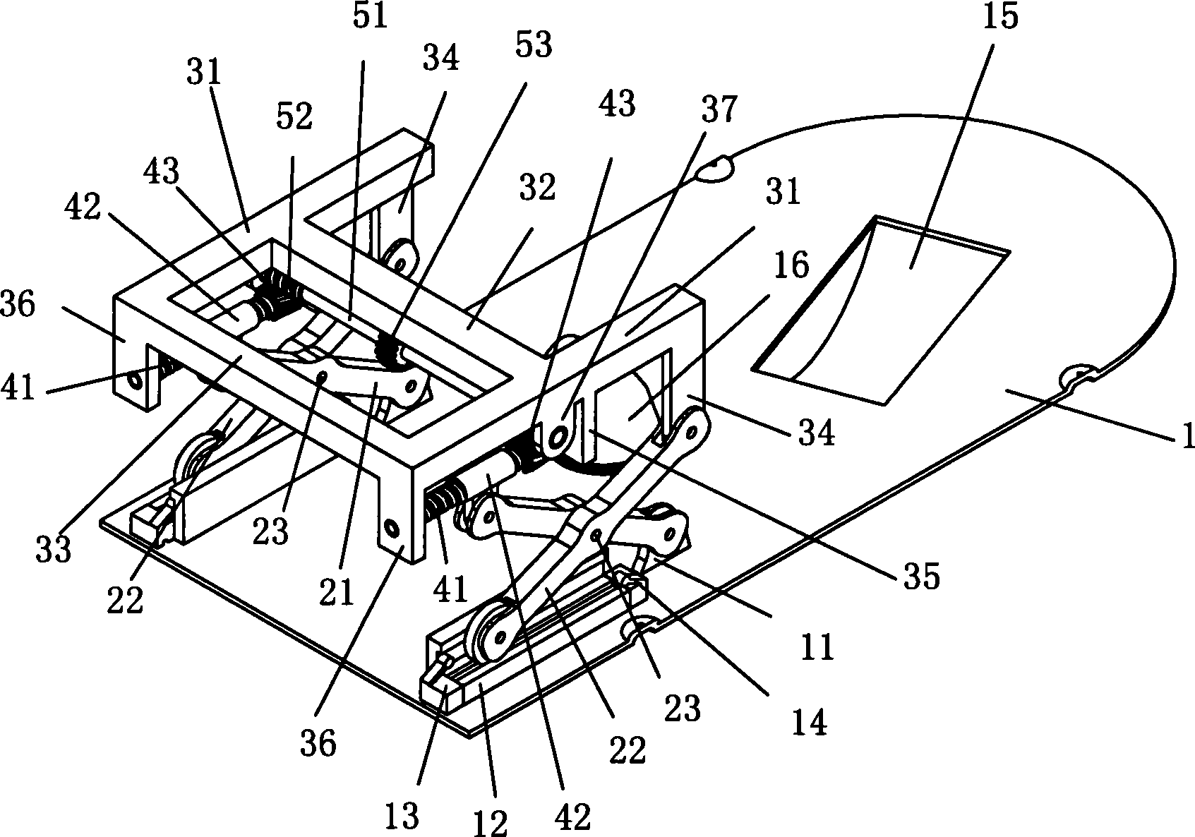
[0016] The structure of an embodiment of the lifting device of the toilet of the present invention driven by a motor, such as figure 1 and figure 2 shown. The lifting device of the toilet has a bottom plate, two sets of X-shaped brackets and a bracket.
[0017] The left and right sides of the bottom plate 1 are respectively provided with an upwardly protruding hinge seat 11, and a longitudinal guide rail 12 is respectively arranged behind each hinge seat 11; a lower limit position detection switch 13 is installed at the rear end of each guide rail 12 , an upper limit position detection switch 14 is installed at the front end of each guide rail 12 . The front portion of the bottom plate 1 is provided with a groove 15 corresponding to the sewage elbow at the sewage outlet at the bottom of the bedpan and a hard elbow 16 connected to the mouth of the sewer. The inner port of the hard elbow 16 can be connected with a U-shaped hose.
[0018] A group of X-shaped supports hinged ...
Embodiment 2
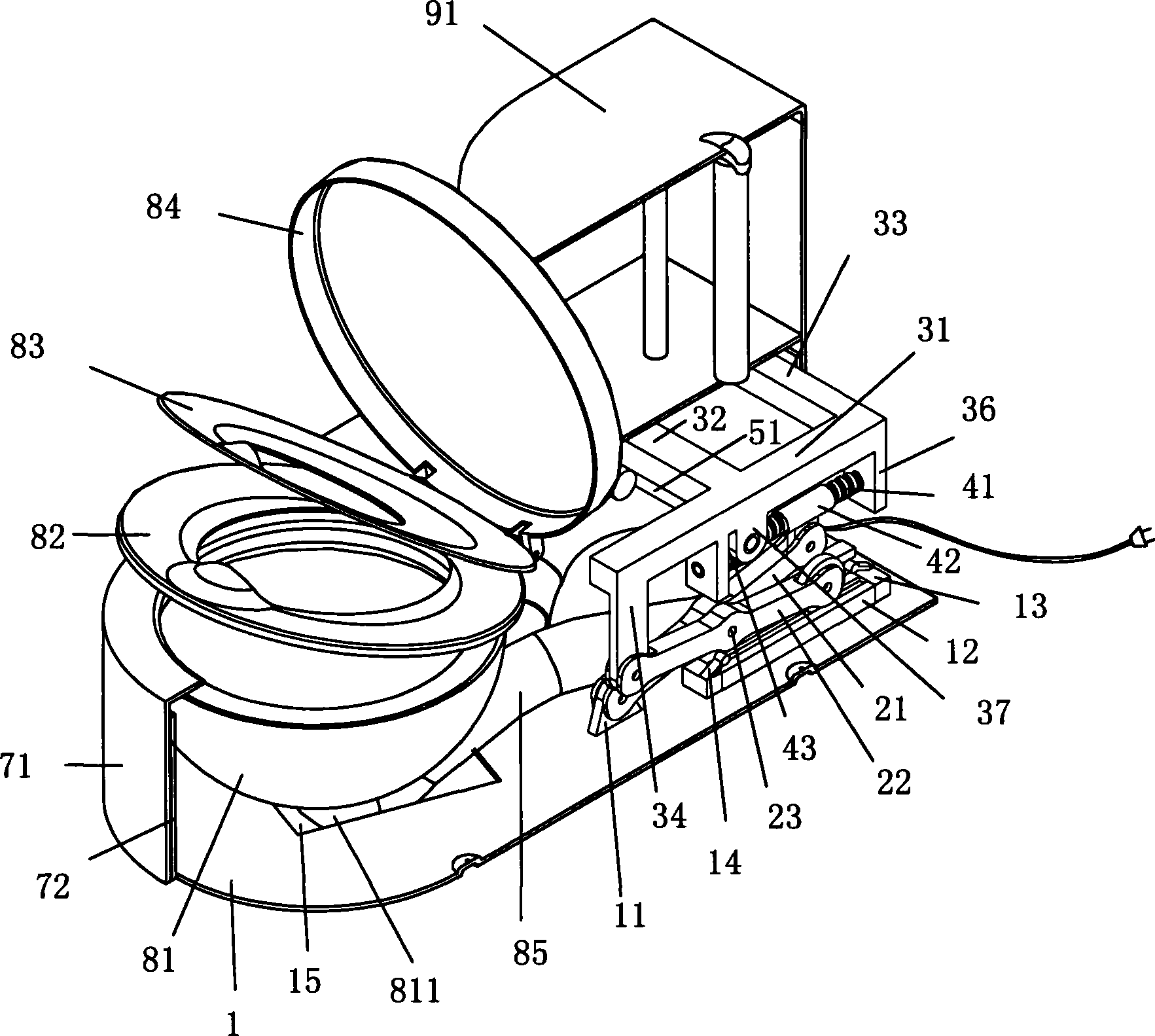
[0027] The structure of a manual operation embodiment of the lifting device of the toilet of the present invention, as Figure 5 shown. The lifting device of the toilet has a bottom plate, two sets of X-shaped brackets and a bracket.
[0028] The left and right sides of the bottom plate 1 are respectively provided with an upwardly protruding hinge seat 11, and a longitudinal guide rail 12 is respectively arranged behind each hinge seat 11; a lower limit position detection switch 13 is installed at the rear end of each guide rail 12 , an upper limit position detection switch 14 is installed at the front end of each guide rail 12 . The front portion of the bottom plate 1 is provided with a groove 15 corresponding to the sewage elbow at the sewage outlet at the bottom of the bedpan and a hard elbow 16 connected to the mouth of the sewer. The inner port of the hard elbow 16 can be connected with a U-shaped hose.
[0029] A group of X-shaped supports hinged by the middle part of...
PUM
 Abstract
Description
Claims
Application Information