
Headlight apparatus of vehicle

A technology for headlamps and vehicles, which is applied in the direction of lighting devices, fixed lighting devices, and parts of lighting devices, etc., and can solve the problems of increasing the upper and lower dimensions of the housing, increasing the size of the headlight device, and the shape and design of the reflector. Constraints and other issues, to achieve the effect of reducing the number of parts, improving the recognizability, and suppressing the increase of the upper and lower dimensions of the shell

Inactive Publication Date: 2009-08-05
HONDA MOTOR CO LTD
View PDF1 Cites 7 Cited by
  • Summary
  • Abstract
  • Description
  • Claims
  • Application Information

AI Technical Summary

Problems solved by technology

[0005] However, in the structure described in Patent Document 1, since the position light bulb is provided directly under the reflector for the headlight bulb, the shape and design of the reflector are easily restricted.
In order to clearly distinguish the position lamp bulb and the headlight bulb and improve the visibility, the vertical distance between the two is increased, and there is a problem that the upper and lower dimensions of the housing are likely to be increased, and the overall size of the headlight device is increased.

Method used


Image

  • Headlight apparatus of vehicle
  • Headlight apparatus of vehicle
  • Headlight apparatus of vehicle

Examples


Embodiment Construction

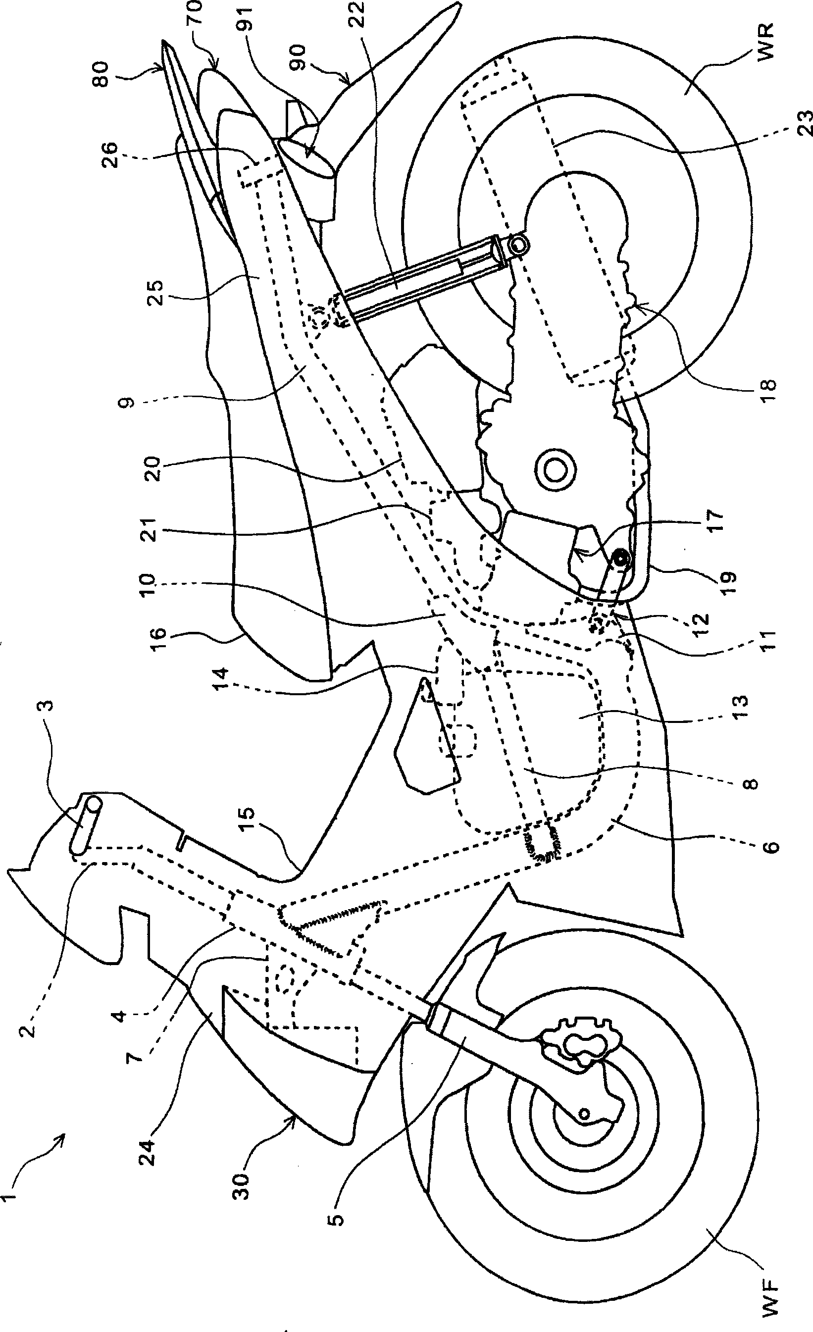
[0032] Preferred embodiments of the present invention will be described in detail below with reference to the accompanying drawings. figure 1 It is a side view of a motorcycle 1 according to an embodiment of the present invention. The automatic two-wheeled vehicle 1 is a scooter-type saddle-riding vehicle equipped with a unit swing type power unit incorporating a continuously variable transmission. A cylindrical head pipe 4 is fixed to the front of the vehicle body of a pair of left and right main frames 6 , and a front wheel WF is rotatably supported by lower ends of a pair of left and right front forks 5 pivotally supported by the head pipe 4 .

[0033] The front wheel WF can be steered by a steering rod 2 connected to a shaft (not shown) rotatably pivotally supported on a head pipe 4 , and the steering rod 2 is provided with a pair of left and right handlebars 3 . The head pipe 4 is covered from the front and rear directions of the vehicle body by the front cover 24 and th...


PUM


Abstract

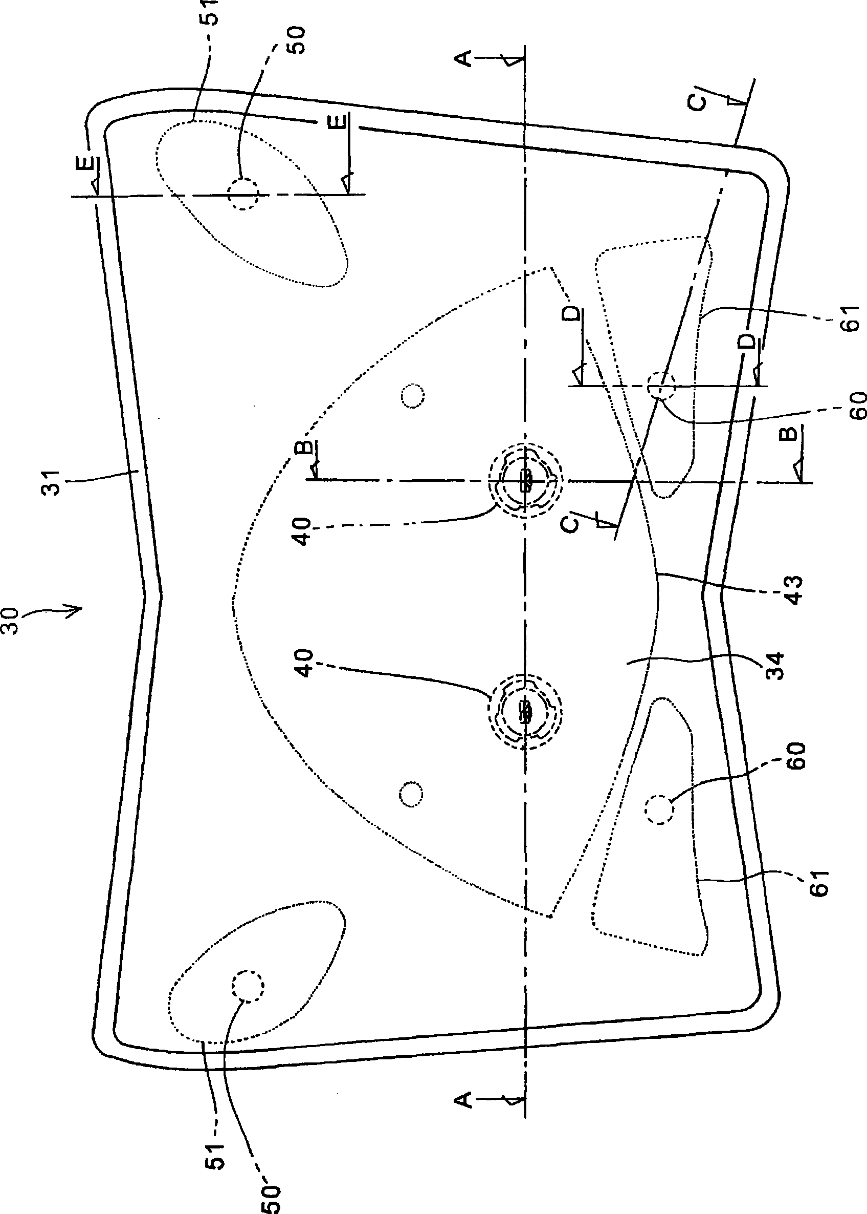
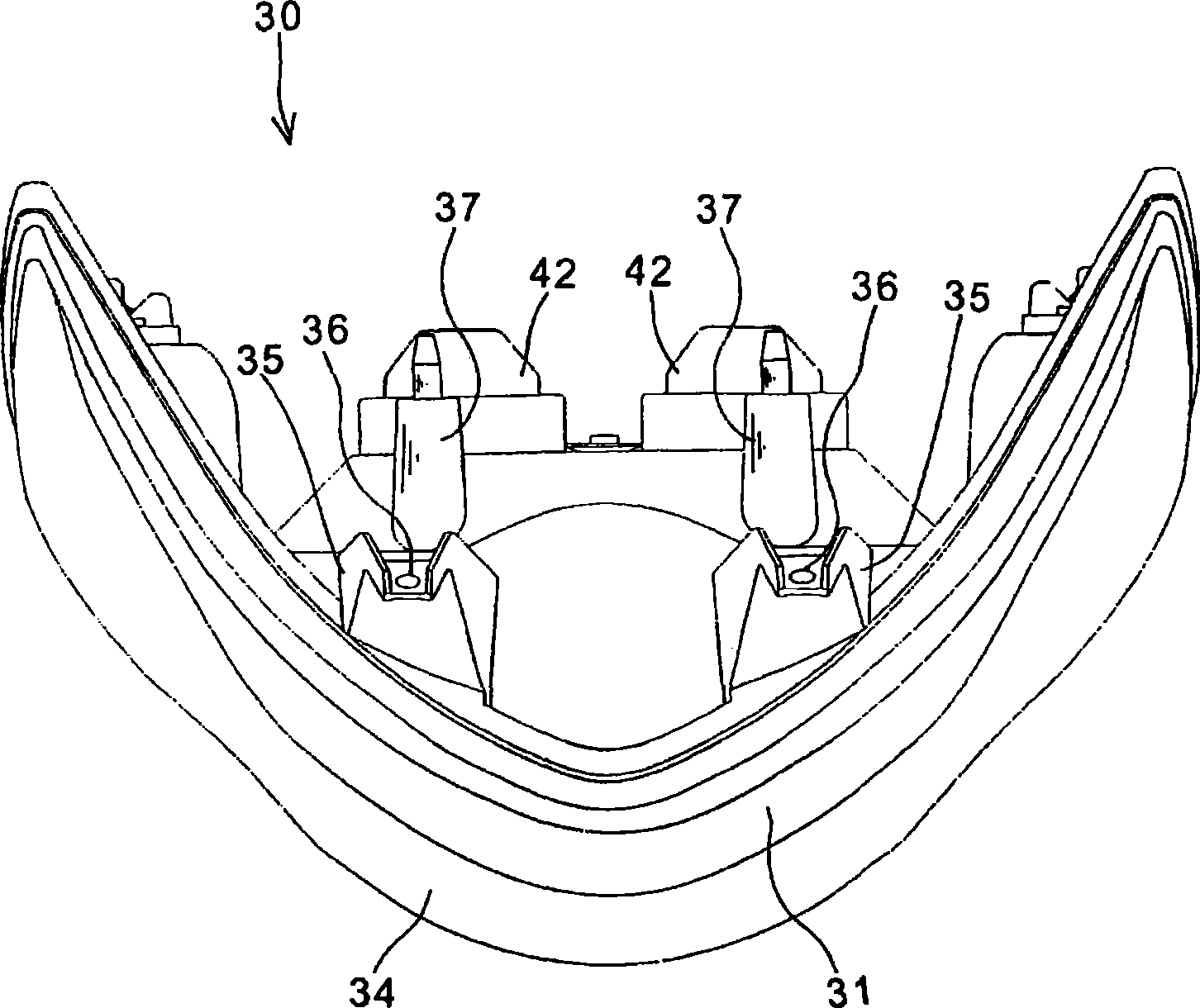
A head light device of vehicle capable of inhibiting enlargement of upper and lower sizes of the head light as well as improving probability of position lamp being identified is provided. The head light and the position lamp are accommodated a head light unit (30) of a single housing (31) and the position lamp bulb (60) is configured in a position on a lower end of a reflector (43) of the head light bulb (40) and in displacement in any one of left and right sides of the width direction. There are a pair of left and right position lamp bulbs (60) in left and right sides in width direction on lower end of the housing (31). A pair of left and right indication lamp bulbs (50) are arranged in left and right sides in width direction on upper end of the head light bulb (40). A pair of left and right head light bulbs (40) is arranged in a gap that is narrower than that of the position lamp bulbs (60). A light guide plate (41) of the head light bulb (40) and a reflector (61) for the position lamp are integrally formed to reduce parts number.

Description

technical field [0001] The present invention relates to a vehicle headlamp device, and particularly to a vehicle headlamp device capable of improving the visibility of a position lamp while suppressing an increase in the vertical size of the headlamp device. Background technique [0002] Conventionally, a headlight device for a vehicle is known in which a headlight and a position lamp are arranged in a single lamp housing. [0003] Patent Document 1 discloses a headlight device for a motorcycle in which a single-lamp position lamp bulb is provided below a single-lamp type headlight bulb. [0004] Patent Document 1: (Japanese) Unexamined Patent Publication No. 2007-280760 [0005] However, in the structure described in Patent Document 1, since the position light bulb is provided directly under the reflector for the headlight bulb, the shape and design of the reflector are easily restricted. If the vertical distance between the two is increased to clearly distinguish the pos...

Claims


Application Information

Patent Timeline
Patent Type & Authority Applications(China)
IPC IPC(8): F21S8/10F21V19/00B62J6/00F21W101/10
Inventor 中岛广幸立石康布恩苏克·埃卡维特
Owner HONDA MOTOR CO LTD
Learn More