Continuous flue gas monitoring electronic refrigerator

An electronic refrigeration and flue gas technology, applied in refrigerators, refrigeration components, refrigeration and liquefaction, etc., can solve the problems of slow heat exchange speed, high energy consumption, and loud noise, and achieve high temperature control accuracy and low energy consumption , the effect of low noise

Inactive Publication Date: 2009-08-05
UNIVERSTAR SCI & TECH SHENZHEN
View PDF0 Cites 7 Cited by
  • Summary
  • Abstract
  • Description
  • Claims
  • Application Information

AI Technical Summary

Problems solved by technology

The heat release surface is cooled by a fan, and the heat absorption surface is close to the refrigeration barrel. When the gas flows through the refrigeration barrel, the moisture in the flue gas will condense into water at a lower temperature, and will be discharged from the condenser to obtain clean gas. For the detection of the analyzer, although this device can perform dehydration and drying treatment of flue gas, it still has the following defects: 1. When the whole device is in a long-term working state, due to the heat dissipation on one side, the efficiency of dehydration and drying treatment of flue gas is low , the refrigerating sheet is often overloaded and burns out. 2. The device uses a semiconductor electronic refrigerating sheet with a heat-absorbing surface close to one end of the refrigerating barrel. When the humid gas is dewatered and dried by the refrigerating barrel, the other end of the refrigerating barrel has an obvious effect of dewatering and drying. The other is to use a compressor to refrigerate. The principle of refrigeration is the same as that of a refrigerator. The compressor compresses the refrigerant (ammonia or freon), the temperature rises, and it enters the radiator, exot...

Method used


Image

  • Continuous flue gas monitoring electronic refrigerator
  • Continuous flue gas monitoring electronic refrigerator
  • Continuous flue gas monitoring electronic refrigerator

Examples


Embodiment Construction

[0015] The present invention will be further introduced below in conjunction with the accompanying drawings and specific embodiments, but not as a limitation of the present invention.

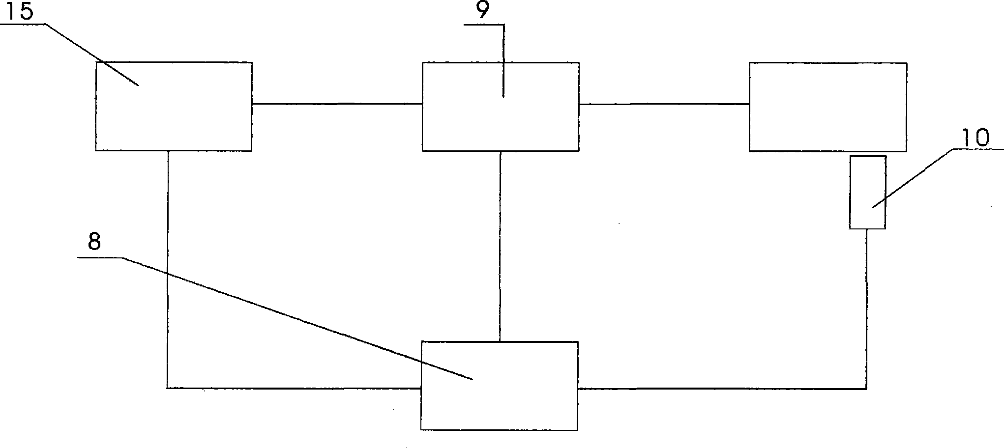
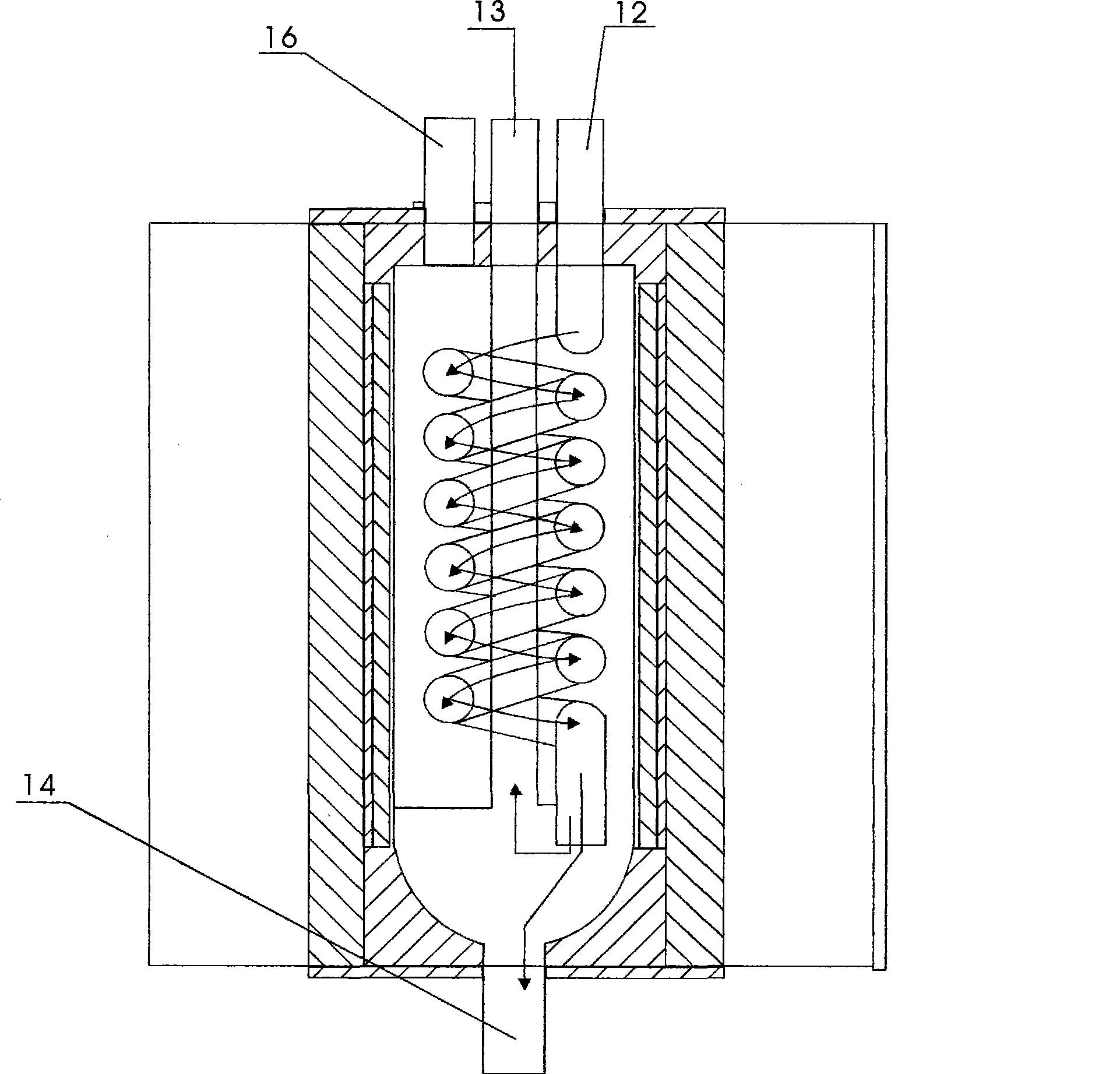
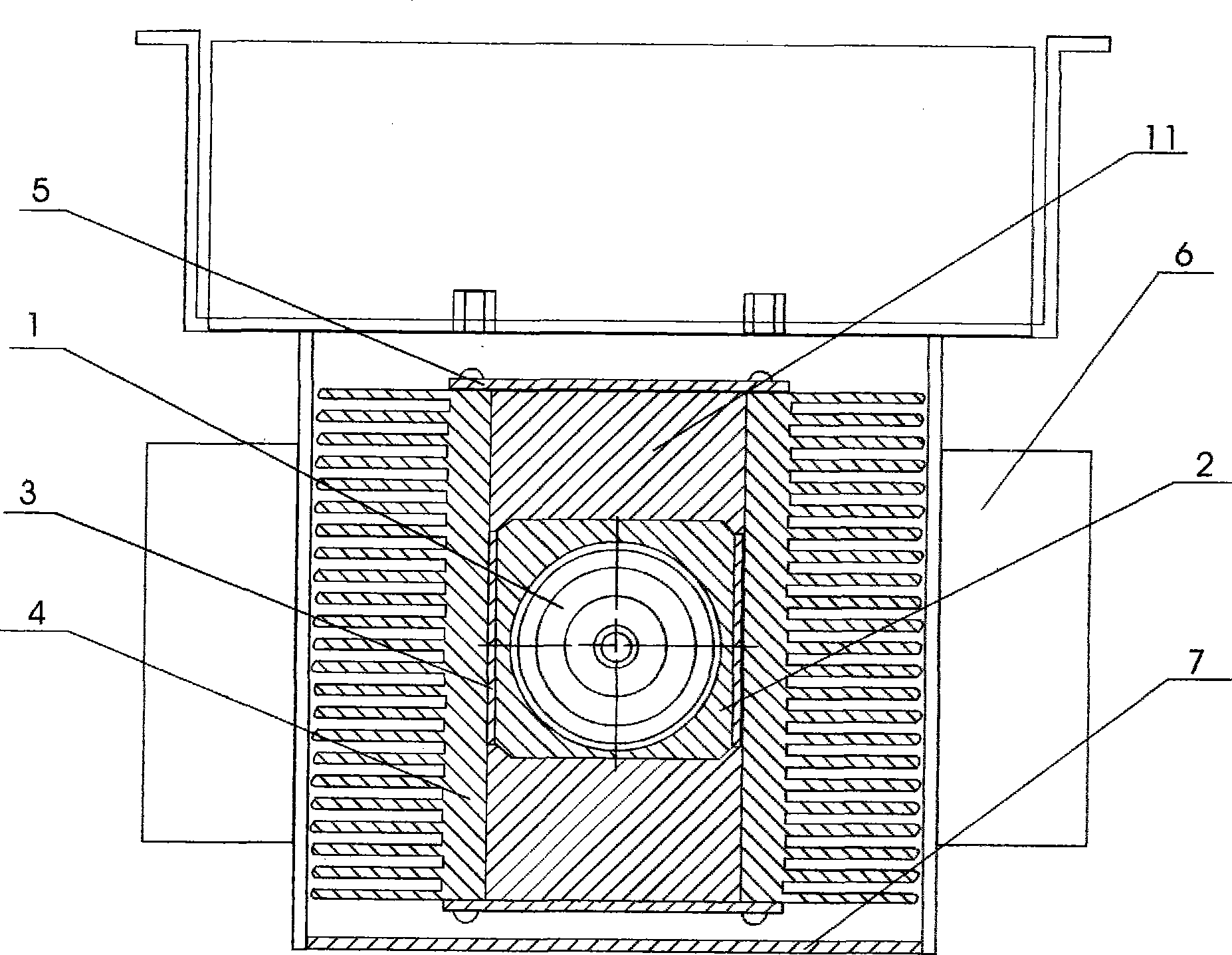
[0016] As shown in the figure, the present invention mainly comprises acid and alkali resistant borosilicate glass tube 1, aluminum aluminum core 2, semiconductor refrigeration sheet 3, cooling fin 4, closing plate 5, cooling fan 6, box body 7, PID (ratio Integral differential control) temperature controller 8, solid state relay 9, platinum resistance temperature sensor 10, characterized in that: the acid and alkali resistant borosilicate glass tube 1 is installed in the aluminum core 2, and the heat-conducting silicone glue The two parts are in complete contact, and the two semiconductor cooling chips 3 are tightly attached to the outer surface of the aluminum aluminum core 2 with heat-conducting silicone grease. The surface is fully contacted with heat-conducting silicone glue, the studs firm...


PUM


Abstract

The invention relates to a flue gas continuous monitoring electronic cooler which mainly comprises an acid and alkali resistance borosilicate glass tube 1, an aluminum-made aluminum core 2, a semiconductor cooling plate 3, a radiating fin 4, a closed plate 5, a cooling fan 6, a box body 7, a PID (PID control) temperature controller 8, a solid state relay 9 and a platinum resistance temperature sensor 10. The temperature of the acid and alkali resistance borosilicate glass tube 1 (namely flue gas to be tested) is accurately controlled by the PID (PID control) temperature controller 8. The PID (PID control) temperature controller 8 can set a temperature value, and has the functions of alarm, code setup, remote control, communication with other equipment, and the like. The device has the advantages of high efficiency, low energy consumption, low cost, little noise, small volume, light weight, no pollution, fast cold and hot exchange speed, high temperature control accuracy, and the like, is widely applied to the field of dewatering and drying treatment for exhaust source flue gas extracted by a fixed pollution source continuous monitor system.

Description

technical field [0001] The invention relates to a device for dewatering and drying treatment of emission source flue gas extracted by a continuous emission monitoring system for fixed pollution sources, in particular to an electronic refrigerator for continuous monitoring of flue gas. Background technique [0002] With the development of society, the advancement of science and technology, and the development of large industries, the requirements for environmental protection are getting higher and higher. Real-time monitoring and real-time processing are required. Therefore, the continuous emission monitoring system of fixed pollution sources is particularly important, and the continuous emission of fixed pollution sources The monitoring system needs to remove water and dry the extracted flue gas from the emission source before sending the treated clean gas to the analyzer for concentration analysis. Because the temperature of the flue gas from the emission source is high, it ...

Claims


Application Information

Patent Timeline
IPC IPC(8): F25B21/02F25B49/00
Inventor 李野
Owner UNIVERSTAR SCI & TECH SHENZHEN
Why Eureka
Try Eureka