
Loading apparatus for chain cable tensile testing machine

A tensile testing machine and loading device technology, which is applied to measuring devices, using stable tension/pressure testing material strength, instruments, etc., can solve the problems of complex structure, high cost of loading devices, heavy total weight, etc., and reduce manufacturing costs. cost, improve work efficiency, prolong the effect of length

Inactive Publication Date: 2009-08-05
JIANGSU UNIV OF SCI & TECH
View PDF0 Cites 29 Cited by
  • Summary
  • Abstract
  • Description
  • Claims
  • Application Information

AI Technical Summary

Problems solved by technology

However, the loading device includes a steel structure mobile frame and a fixed frame consisting of four beams, two longitudinal beams, two tie rods and matching tie rod nuts, the structure is complex, the number of steel structures and forgings is large, and the total weight is heavy
In order to meet the requirements of different lengths of anchor chain tensile test sections of different specifications, the stroke of the loading cylinder of the loading device is longer, such as the stroke of the loading cylinder of the 12MN anchor chain tensile testing machine reaches 2.3 meters, which increases the manufacturing cost of the loading cylinder
In order to meet the requirements of large tensile loads, beams, longitudinal beams, grooved locking beams, tie rods, tie rod nuts, and tension fixtures are high-strength, rigid, large-tonnage steel structural parts and casting and forging parts, which are expensive and difficult to process. , resulting in a high cost of the loading device of the continuous semi-automatic anchor chain tensile testing machine

Method used


Image

  • Loading apparatus for chain cable tensile testing machine
  • Loading apparatus for chain cable tensile testing machine
  • Loading apparatus for chain cable tensile testing machine

Examples


Embodiment Construction

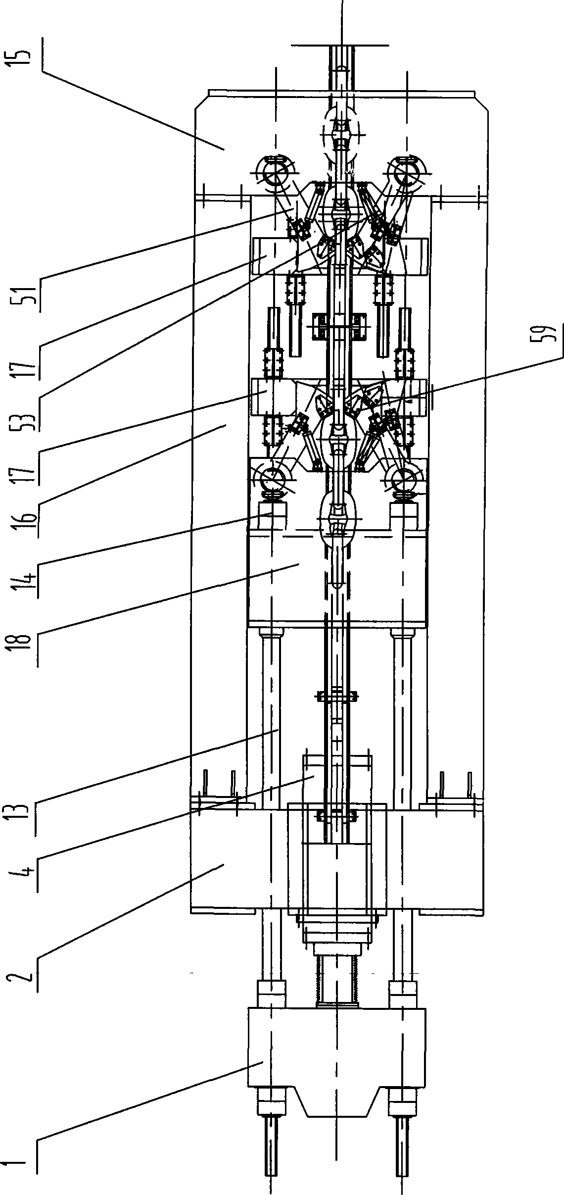
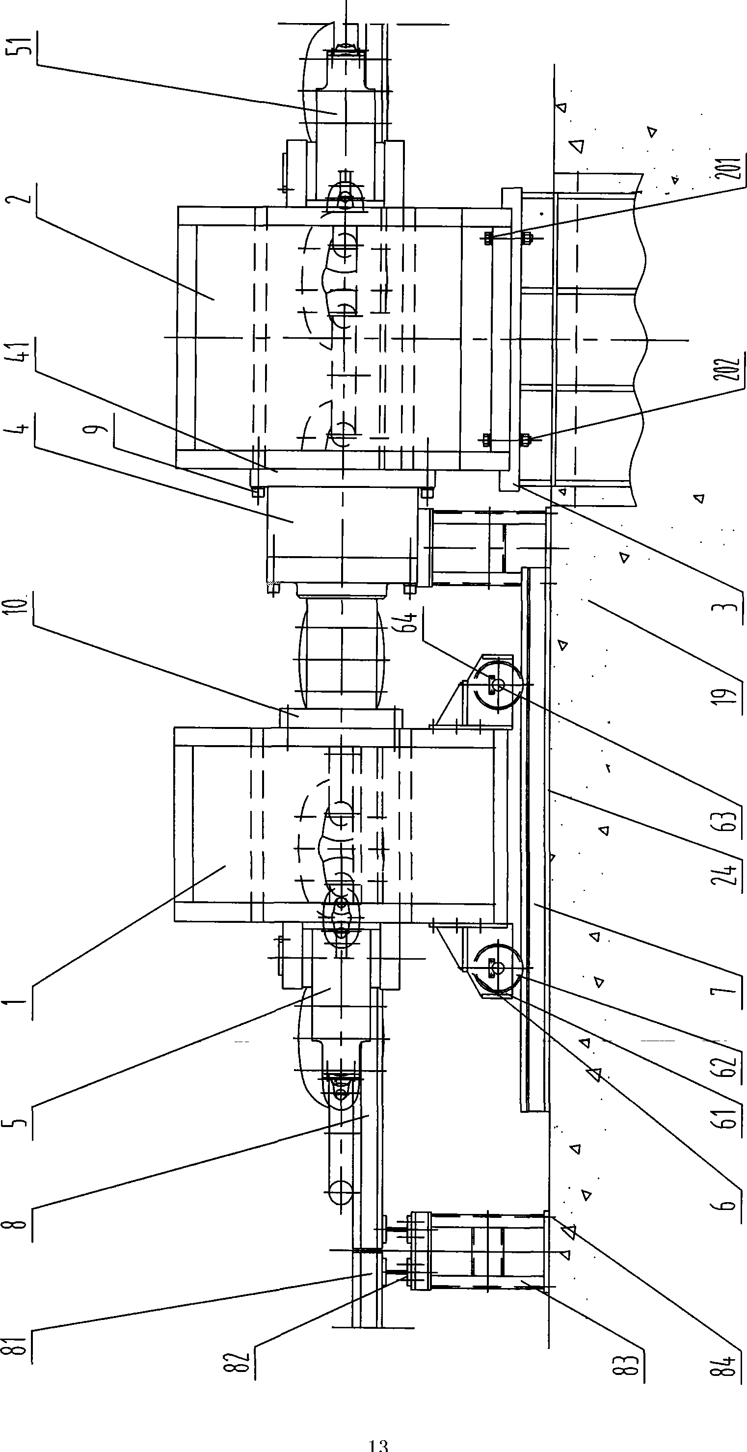
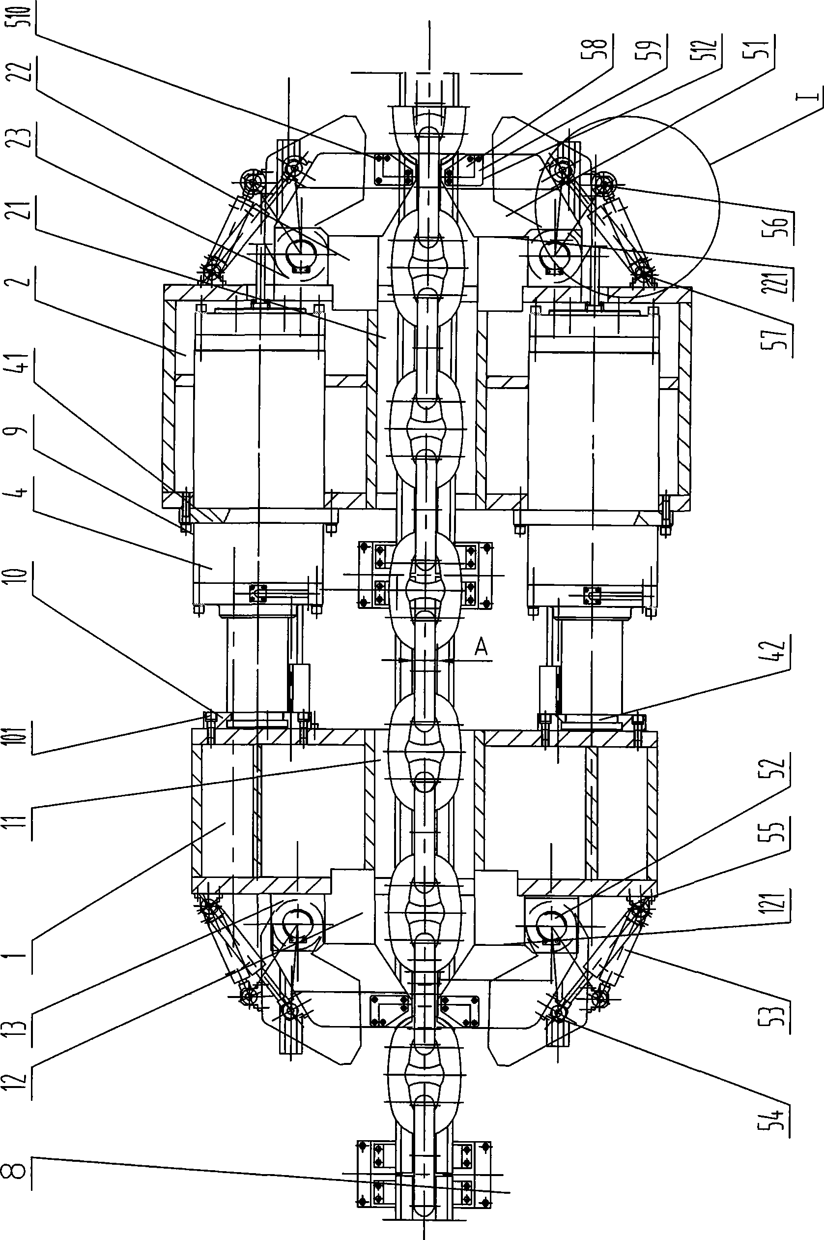
[0029] The present invention will be further described below in conjunction with drawings and embodiments.

[0030] This embodiment takes the loading device of a 12MN continuous semi-automatic anchor chain tensile testing machine as an example.

[0031] see figure 2 , image 3 and Figure 4, The present invention includes a moving beam 1, a fixed beam 2, a fixed beam base 3, a double loading cylinder 4, an anchor chain ring clamping device 5, a moving device 6, a track 7 and an anchor chain support rail device 8. The fixed beam base 3 is buried in the concrete foundation 19 , and the bottom surface of the fixed beam 2 and the top surface of the fixed beam base 3 are fixedly connected by bolts 201 and nuts 202 . Two loading cylinders 4 are symmetrically arranged in the fixed beam 2 along the length direction of the fixed beam 2, the mounting flange 41 of the loading cylinder 4 is fixedly connected with the front side of the fixed beam 2 by screws 9, and the piston rod head ...


PUM


Abstract

The invention discloses a charger of an anchor chain tension tester, which comprises a movable cross beam, a fixed cross beam, a fixed cross beam base, load oil cylinders, anchor chain link clamping devices and mobile devices, wherein the fixed cross beam base is buried in a concrete foundation, the lower side of the fixed cross beam is fixedly connected with the fixed cross beam base; the two load oil cylinders are symmetrically arranged in the fixed cross beam along the length direction of the fixed cross beam, and piston rod heads of the load oil cylinders are respectively fixedly connected with the rear side of the movable cross beam by symmetrically arranged pairing flanges; the mobile devices are arranged in pair between the top surface of a railway and the lower side of the movable cross beam; and the anchor chain link clamping devices are respectively arranged at the front side of the movable cross beam and the rear side of the fixed cross beam. The invention can perform the tension test on offshore oil platform mooring anchors with the length of several hundred meters or several thousand meters, reduces the manufacture cost of the charger, extends the length of the tested anchor chain link, reduces the test frequency and enhances the work efficiency.

Description

technical field [0001] The invention relates to a loading device of a testing machine, in particular to a large force value loading device for anchor chain tension testing, and belongs to the technical field of horizontal special tensile testing machines. Background technique [0002] High-strength and large-scale marine anchor chains and offshore oil platform mooring anchor chains are important facilities related to the safety of oceangoing, offshore, inland ships and offshore oil platforms. ) needs to work for a long time under the action of periodic load, and it is essential to detect the mechanical properties of the anchor chain. The relevant specifications of each classification society and the relevant international standards and national standards stipulate that after the heat treatment of the anchor chain, all chain links must be subjected to tensile tests according to the tensile load values ​​specified in different specifications and strength levels. Although the c...

Claims


Application Information

Patent Timeline
IPC IPC(8): G01N3/02G01N3/08
Inventor 周云祥刘振钢
Owner JIANGSU UNIV OF SCI & TECH
Learn More