Shutter opening and closing mechanism for withdrawn type high-voltage switch cabinet

A technology of high-voltage switchgear and opening and closing mechanism, which is applied to the protection plate/protection device of switchgear, substation/switch arrangement details, electrical components, etc. Synchronization is easy to guarantee, avoid jamming and loosening, and the effect of safety guarantee

Inactive Publication Date: 2009-08-05
ANHUI NANRUI JIYUAN POWER GRID TECH CO LTD
View PDF0 Cites 13 Cited by
  • Summary
  • Abstract
  • Description
  • Claims
  • Application Information

AI Technical Summary

Problems solved by technology

[0003] 1. When the handcart is in the removed position, the valve is not locked, and the valve can be opened at will, and the electrical safety cannot be guaranteed
[0004] 2. Due to the "flat opening" structure, after the valve is opened, the electrical gap between the upper and lower valves and the high-voltage live part is only about 180mm, which is lower than the 300mm stipulated in the national standard. It can only be completed by composite insulation. Once the environment Changes in conditions or aging of insulation can easily cause discharge and even lead to breakdown
[0005] 3. When the steel wire rope drives the rollers to move up and down in the slots of the left and right side panels, it is easy to get stuck, and it is not easy to ensure the synchronization of the left and right sides
[0006] 4. The assembly is troublesome, especially the fixing of the wire rope. The wire rope needs to be fixed at the end of the fixed rope pin and the nut, and the installation needs to be installed on the back of the left and right side panels. The wire rope may also loosen during the movement.

Method used


Image

  • Shutter opening and closing mechanism for withdrawn type high-voltage switch cabinet
  • Shutter opening and closing mechanism for withdrawn type high-voltage switch cabinet
  • Shutter opening and closing mechanism for withdrawn type high-voltage switch cabinet

Examples


Embodiment Construction

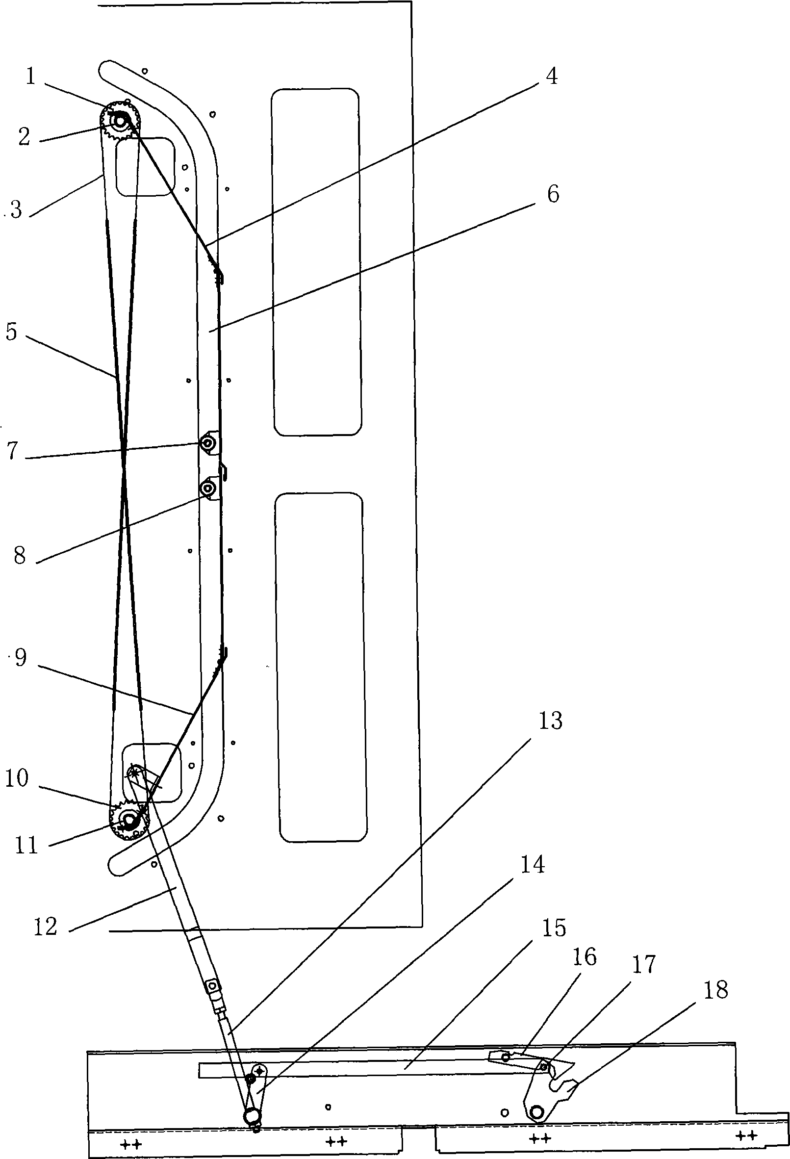
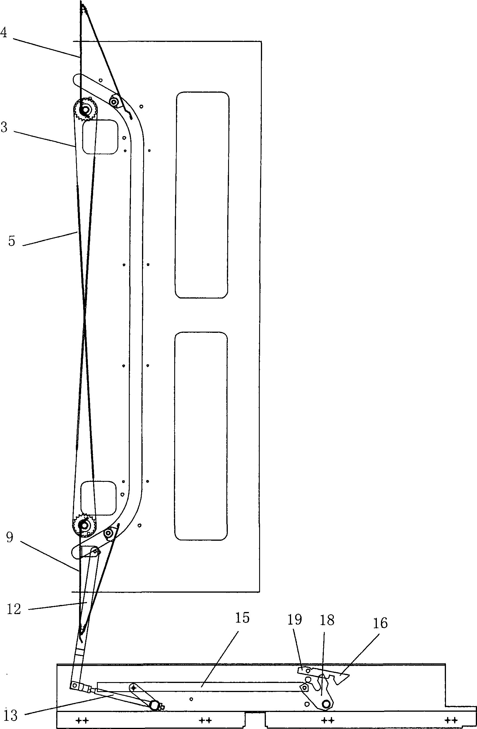
[0031] see figure 1 , figure 2 , in this embodiment, the upper valve, the lower valve and the valve opening and closing mechanism are installed symmetrically up and down in the circuit breaker room of the switch cabinet; wherein:

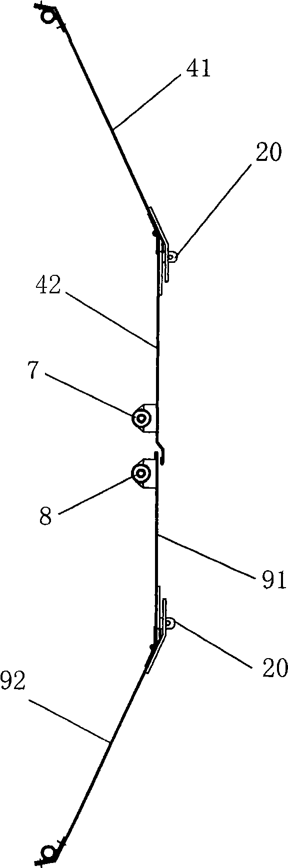
[0032] see image 3 , the upper valve 4 and the lower valve 9 are respectively by the upper door plate 41 of the upper valve and the lower door plate 42 of the upper valve, and the upper door plate 91 of the lower valve and the lower door plate 92 of the lower valve. A lock nose 20 that can be locked between the upper door panel, the lower door panel 42 and the lower valve upper door panel 91 is provided at the overlapping position of the upper door panel and the lower door panel;

[0033] figure 1 , figure 2 As shown, upper slide 7 and lower slide 8 are respectively fixed on the left and right sides of upper valve 4 and lower valve 9, and upper valve 4 and lower valve 9 can pass through upper slide 7 and lower slide 8 respectively. The "conc...


PUM


Abstract

The invention relates to a valve opening and closing mechanism with an interlock for a movable high-voltage switch cabinet, which comprises an upper valve, a lower valve and a valve opening and closing mechanism. The upper valve and the lower valve are arranged on a circuit breaker chamber of the switch cabinet in a longitudinal symmetry way. The mechanism is characterized in that the upper valve and the lower valve are foldable valves respectively formed by linking an upper valve plate with a lower valve plate through hinges; the left sides and the right sides of the upper valve and the lower valve are respectively fixed with an upper slide block and a lower slide block; and the upper valve and the lower valve can respectively slide along concave slide grooves arranged at the left side and the right side of the circuit breaker chamber through the upper slide block and the lower slide block. The mechanism has the advantages of convenient installation, synchronous starting and no clamping stagnation, and the electrical clearance meets the international standard, and can realize the functions of interlock and padlock.

Description

technical field [0001] The invention relates to a valve opening and closing mechanism of a removable high-voltage switch cabinet, and belongs to the technical field of safety protection facilities for high-voltage switch cabinets. Background technique [0002] In the high-voltage switchgear of the power system, safe operation is the most important performance index, and the valve mechanism provides good personal safety protection for the high-voltage switchgear in the maintenance state. Among the commonly used valve mechanisms at present, the more typical one is the pulley transmission mechanism. The upper and lower valves are driven by wire ropes and movable pulleys, and are composed of movable pulleys, fixed pulleys, fixed rope pins, connecting rods, and guide pieces. When the handcart is pushed from the test position to the working position, the push shaft of the valve pushes against the moving guide and rotates around the shaft, and the lower valve is driven to open down...

Claims


Application Information

Patent Timeline
Patent Type & Authority Applications(China)
IPC IPC(8): H02B1/38H02B1/30H02B1/26
CPCH02B11/24
Inventor 朱跃葛晖陈华谢理华何其新李宝仓刘吉利王坦坦陈菊
Owner ANHUI NANRUI JIYUAN POWER GRID TECH CO LTD
Why Eureka
Try Eureka