
Method and processing machine for tensioned processing of complex contours of asymmetric workpieces

An asymmetric, workpiece technology, applied in metal processing, metal processing equipment, turning equipment, etc., to avoid acceleration force jumps, safety and cost savings

Inactive Publication Date: 2009-08-12
SMS MEER
View PDF0 Cites 10 Cited by
  • Summary
  • Abstract
  • Description
  • Claims
  • Application Information

AI Technical Summary

Problems solved by technology

The invention is based on the insight that, thanks to the tool running horizontally to the disc, it is no longer necessary to drive the disc up and down, thus eliminating the need for a tool in existing turning machines because there is no longer any problem of positioning angles. Indispensable Y-axis for vertical positioning of the turning tool with respect to the side workpiece surface

Method used


Image

  • Method and processing machine for tensioned processing of complex contours of asymmetric workpieces
  • Method and processing machine for tensioned processing of complex contours of asymmetric workpieces
  • Method and processing machine for tensioned processing of complex contours of asymmetric workpieces

Examples


Embodiment Construction

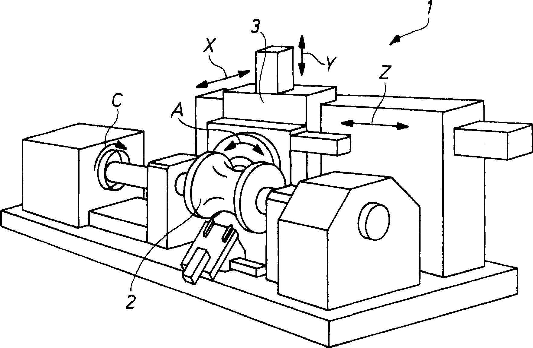
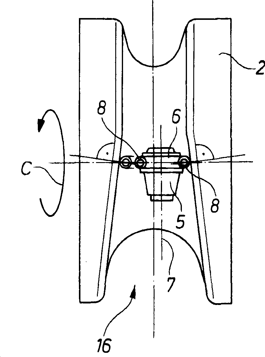
[0017] figure 1 A lathe 1 belonging to the prior art is shown in, which is used to produce workpieces with complex asymmetric contours through turning processing, especially such as Pilger roll 2 (see also image 3 ). The workpiece / pilger roll 2 is inserted rotatably around the workpiece rotation axis C. The turning tool not shown in the figure can be adjusted around the rotation axis A, and the turning tool can move on the rotating workpiece 2 along the tool main drive axis Z by means of the tool slide 3. The turning tool / tool ​​performs entry and feed movement (X axis) and has the Y axis required to position the turning tool perpendicular to the side surface of the workpiece.

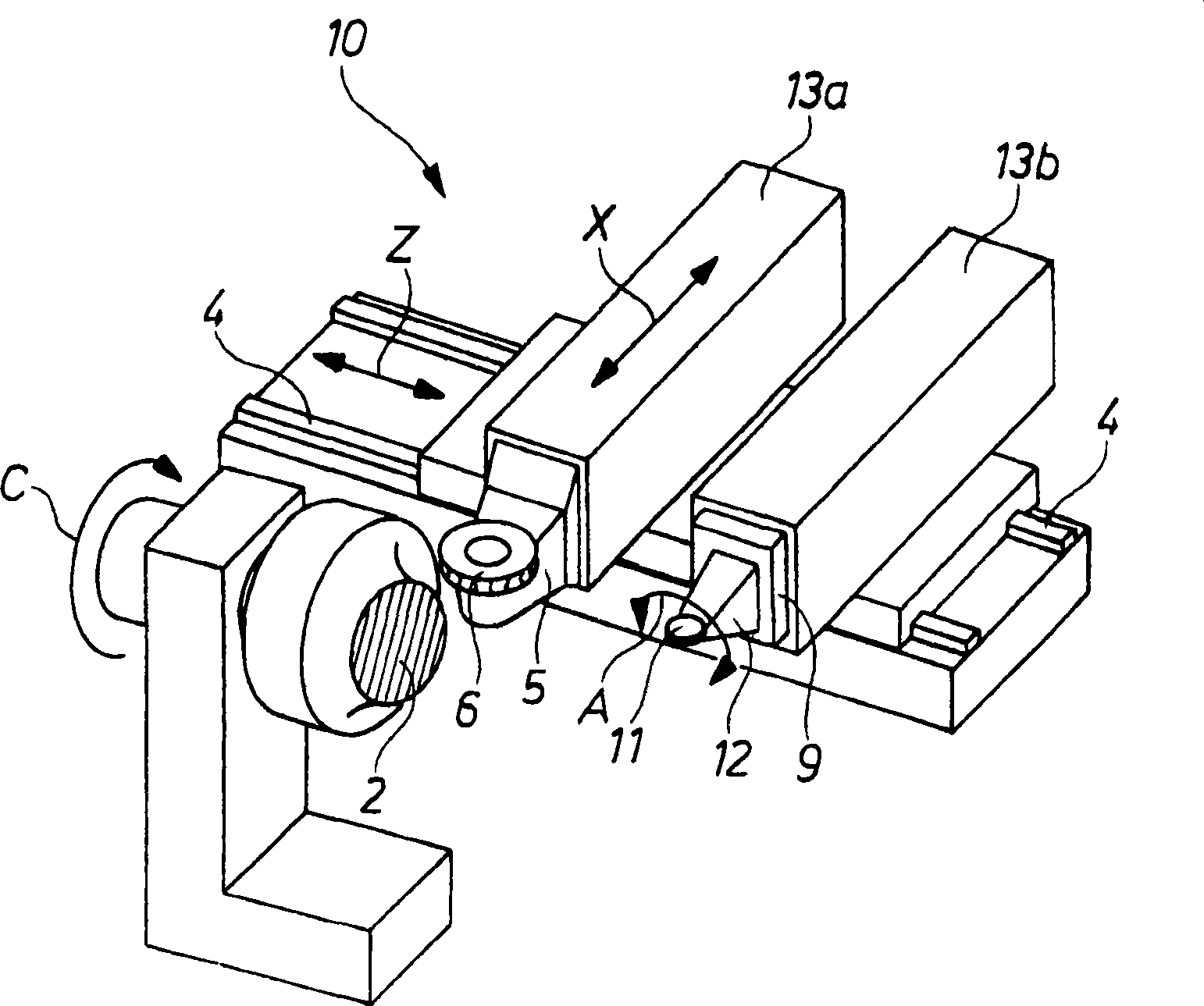
[0018] in figure 2 The processing machine 10 shown in a cut-out manner is configured as a turning and milling machine. The workpiece 2 rotating around the workpiece rotation axis C is equipped with two tool slides 13a or 13b on the linear guide 4 which can move in the Z direction and can cut in the X d...


PUM


Abstract

The invention relates to a method and a processing machine for tensioned processing of complex contours of asymmetric work pieces, specially relates to a method and a processing machine for tensioned processing complex contours of asymmetric work pieces such as pilger rolling on a computer-controlled processing machine. In prior machinery design, complex contour can be obtained by the same cutting speed of cutters and relatively low acceleration force. According to the invention, the method involves machining a work piece by turning and milling with circular plates (11) as a cutting tool on amachine, wherein a tuning is carried out for rotationally symmetrical contour areas of the work piece, and a milling is carried out for asymmetrical contour areas of the work piece.

Description

Technical field [0001] The present invention relates to a method for cutting complex contours of asymmetric workpieces, such as Pilger rolls, on a computer-controlled processing machine and a processing machine implementing this method. Background technique [0002] In order to perform non-circular turning, for example, especially to produce Pilger rolls, a hot Pilger roll processing machine with a computer numerical control device is used in actual work. For Pilger rolls, non-traditional shapes with wider entrances are accompanied by constantly changing cutting angles and lathe tool clearance angles during non-circular cutting. The entrances have a large offset from the rotation axis of the roll. Among them, due to the change of the cutting angle, the cutting force changes greatly. [0003] Therefore, the common hot Pilger roll processing machine in practice requires a machine configuration solution with five controllable axes, in which higher acceleration forces such as inertia...

Claims


Application Information

Patent Timeline
IPC IPC(8): B23P13/02B23P15/30
CPCB23B5/10B23B2270/56B23C3/34B23B3/065B23C7/02
Inventor K·-J·埃瑟E·普拉茨米勒H·-P·施米特A·扎贝尔R·德里克斯K·-J·埃瑟H·-P·施米特
Owner SMS MEER
Learn More