Flat TV frame with remote-control regulated view angle

A technology for adjusting the angle of view of TV racks, which is applied to TVs, color TVs, machine sets/brackets, etc. It can solve the problems of complexity, TV body thickness, and rack body thickness increase, so as to reduce the space for placement and facilitate Operation and production, the effect of simple structure

Inactive Publication Date: 2009-08-12
于英杰
View PDF2 Cites 4 Cited by
  • Summary
  • Abstract
  • Description
  • Claims
  • Application Information

AI Technical Summary

Problems solved by technology

If a better viewing angle adjustment effect is obtained, the thickness of the rack body is increased
In addition, the pendulum shaft and connecting plate included in the TV bracket are all set at the center of the frame body. When the screen rotates, there must be enough room for rotation between the back of the TV body and the wall. The existence of the first casing and the second casing both make the TV body thicker
Because the design tends to be complicated, there are some problems in the practicality of the rack, the aesthetics of the decoration, and the economy of production.

Method used


Image

  • Flat TV frame with remote-control regulated view angle
  • Flat TV frame with remote-control regulated view angle
  • Flat TV frame with remote-control regulated view angle

Examples


Embodiment

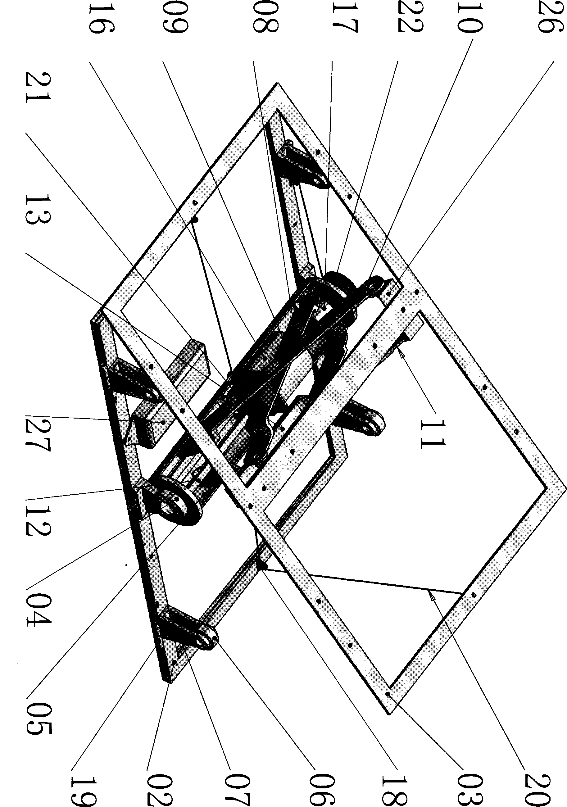
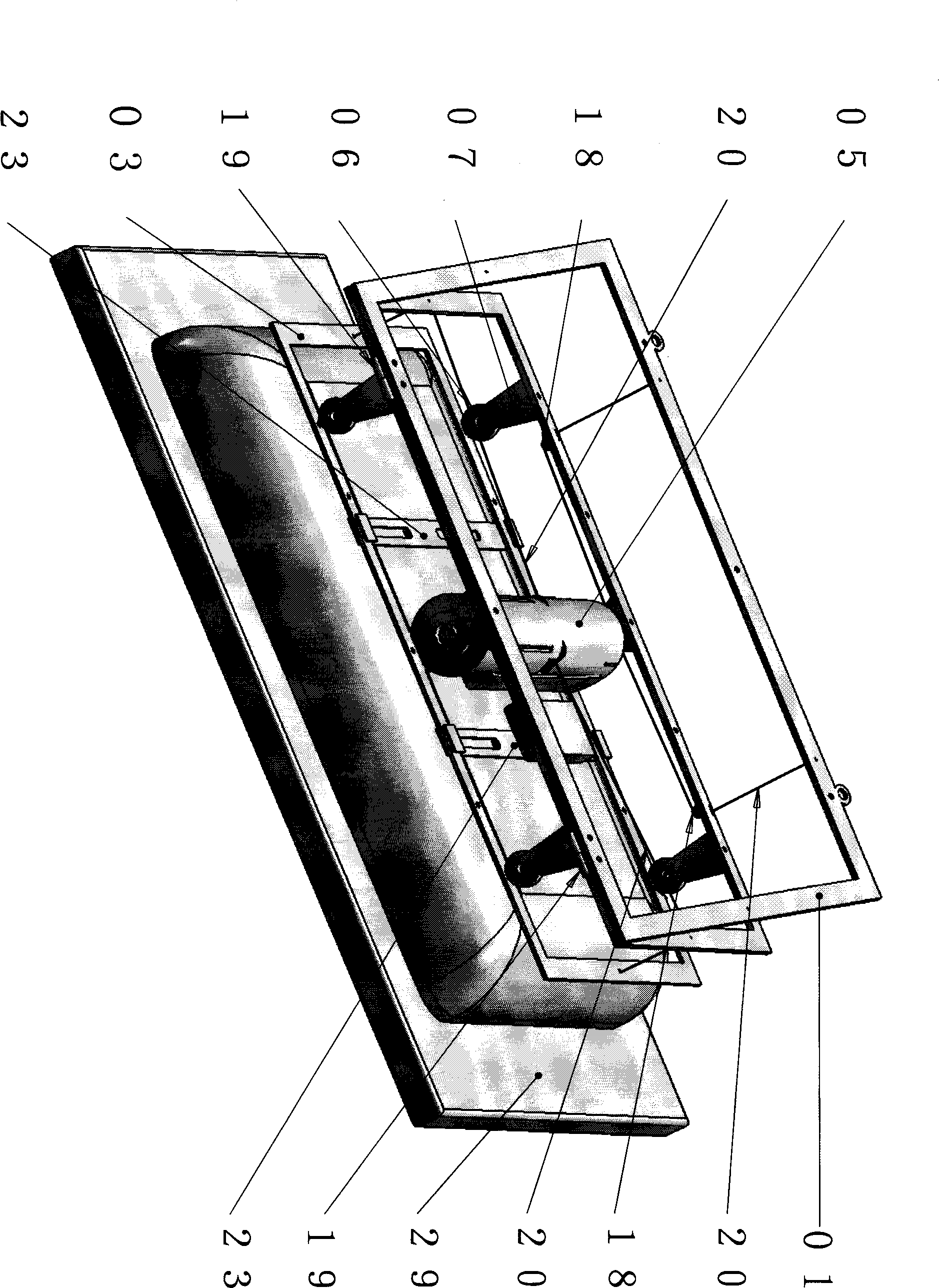
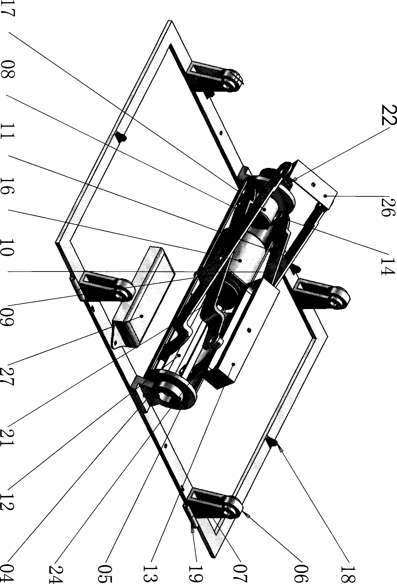
[0021] Embodiment: The flat panel TV frame is designed using the principle of leverage and the linkage mechanism of spliced ​​plates.

[0022] Such as figure 2 , the flat panel TV 29 is connected with two TV connecting plates 23 fixed on the TV back frame 03 . The fulcrum wheel 06 cooperates with the fulcrum wheel frame 07 bearing fixed on the carrier back frame 02. Such as figure 1 , the motor 16 is fixed on the cylindrical supporting plate 05 left and right, and the left and right winding wheels 21 are assembled on the motor rotating shaft. When the motor 29 rotates counterclockwise from left to right, the traction steel rope 20 pulls the left end of the TV back frame 03 through the wire wheel 18, and the left end of the TV back frame 03 is subjected to tension, with the fulcrum wheel 06 as the fulcrum, the right end pushes up at a large distance, and the TV screen turns to the left. turn. When motor 29 rotates clockwise from left to right, as mentioned above, the TV sc...


PUM


Abstract

The invention relates to a panel TV set frame with remote control viewing angles, which consists of a wall back frame, a mechanism supporting body, a TV set connecting body and an electrical control box, wherein the wall back frame and the mechanism supporting body are connected and fixed on a middle part of the mechanism supporting body through a rotating shaft hinge and a pulling wire cable; the mechanism supporting body comprises a part supporting back frame, a pivot mechanism fixed on the part supporting back frame, a panel splicing and linking mechanism and four thread guide pulleys assembled on the part supporting back frame; the panel splicing and linking mechanism comprises a main shaft support, a tube-shape supporting plate, a left-right motor for assembled with left and right reels, a pitching motor assembled with upper and lower reels, an inner slide, an inner hinged support and two groups of splicing panels assembled with panel end wheels; the electrical control box is provided with a circuit board for receiving remote control signals and controlling the left-right motor and the pitching motor; and the power of the panel TV set frame is realized by winding the wire cable. The panel TV set frame has the advantages by taking a left border line, a right border line and a low border line of a screen as rotating shafts to realize the arbitrary remote control adjustment of the screen viewing angles of the panel TV set.

Description

technical field [0001] The invention relates to a flat-panel TV stand, in particular to a flat-panel TV stand for adjusting the viewing angle by remote control. Background technique [0002] In the prior art, there are various structural designs of flat panel television frames. Patent application 200810010902.8, patent application 200820011935, and patent application No. CN101363568A and other patent applications disclose flat-panel TV frame structures, and their structural designs have their own characteristics, but these structural designs have defects in different aspects. [0003] For example, the application numbers are: 200810010902.8 and the design of 200820011935. This is the applicant's application. The wall-mounted TV frame includes a base and an adjustment mechanism connected to the base. The positioning support column and positioning transmission of the adjustment mechanism A truss linkage rod is installed between the sliding columns. The active slider and the p...

Claims


Application Information

Patent Timeline
IPC IPC(8): F16M13/02F16M11/18H04N5/64
Inventor 于英杰
Owner 于英杰
Why Eureka
Try Eureka