Needle shield and interlock

a technology of interlocking and needles, applied in the direction of catheters, intravenous devices, needles infusion, etc., can solve the problems of blood dripping from the needle tip or coming into contact with other surfaces, presenting numerous potential hazards to the clinicians and others in the area, and reducing blood exposure.

Active Publication Date: 2009-12-17
BECTON DICKINSON & CO
View PDF20 Cites 66 Cited by
  • Summary
  • Abstract
  • Description
  • Claims
  • Application Information

AI Technical Summary

Benefits of technology

[0006]The systems and methods of the present disclosure have been developed in response to problems and needs in the art that have not yet been finally resolved by currently available vascular access systems and methods. Thus, these systems and methods are developed to provide safer vascular access systems that reduce blood exposure.

Problems solved by technology

The separation of the needle assembly from the catheter portions of the catheter assembly presents numerous potential hazards to the clinicians and others in the area.
As indicated above, there is a risk of accidental needle sticks if the needle tip is not secured properly in a needle tip shield.
As the needle is withdrawn, there is a risk that this blood will drip from the needle tip or come into contact with other surfaces to expose clinicians and equipment to blood.
Additionally, it has been observed that withdrawing a needle from a catheter assembly often imparts energy to the needle assembly, such as by the intentional or unintentional bending forces applied to the needle during removal.
This energy has been observed to cause blood to splatter or spray from the needle as the needle wiggles and shakes with the stored energy once it is free from the catheter assembly.
While prior needle assemblies have provided needle tip shields to reduce the occurrence of needle sticks, these prior enclosures and clips have not sufficiently addressed the risk that clinicians and equipment may be exposed to blood from the needle without experiencing a needle stick.
While the problem of blood exposure from needle tips used in over-the-needle catheters is a common problem, blood exposure risks are also problematic in other uses of hypodermic needles where the needle tip has been in contact with blood.

Method used


Image

  • Needle shield and interlock
  • Needle shield and interlock
  • Needle shield and interlock

Examples


Embodiment Construction

[0027]The presently preferred embodiments of the present invention will be best understood by reference to the drawings, wherein like reference numbers indicate identical or functionally similar elements. It will be readily understood that the components of the present invention, as generally described and illustrated in the figures herein, could be arranged and designed in a wide variety of different configurations. Thus, the following more detailed description, as represented in the figures, is not intended to limit the scope of the invention as claimed, but is merely representative of presently preferred embodiments of the invention.

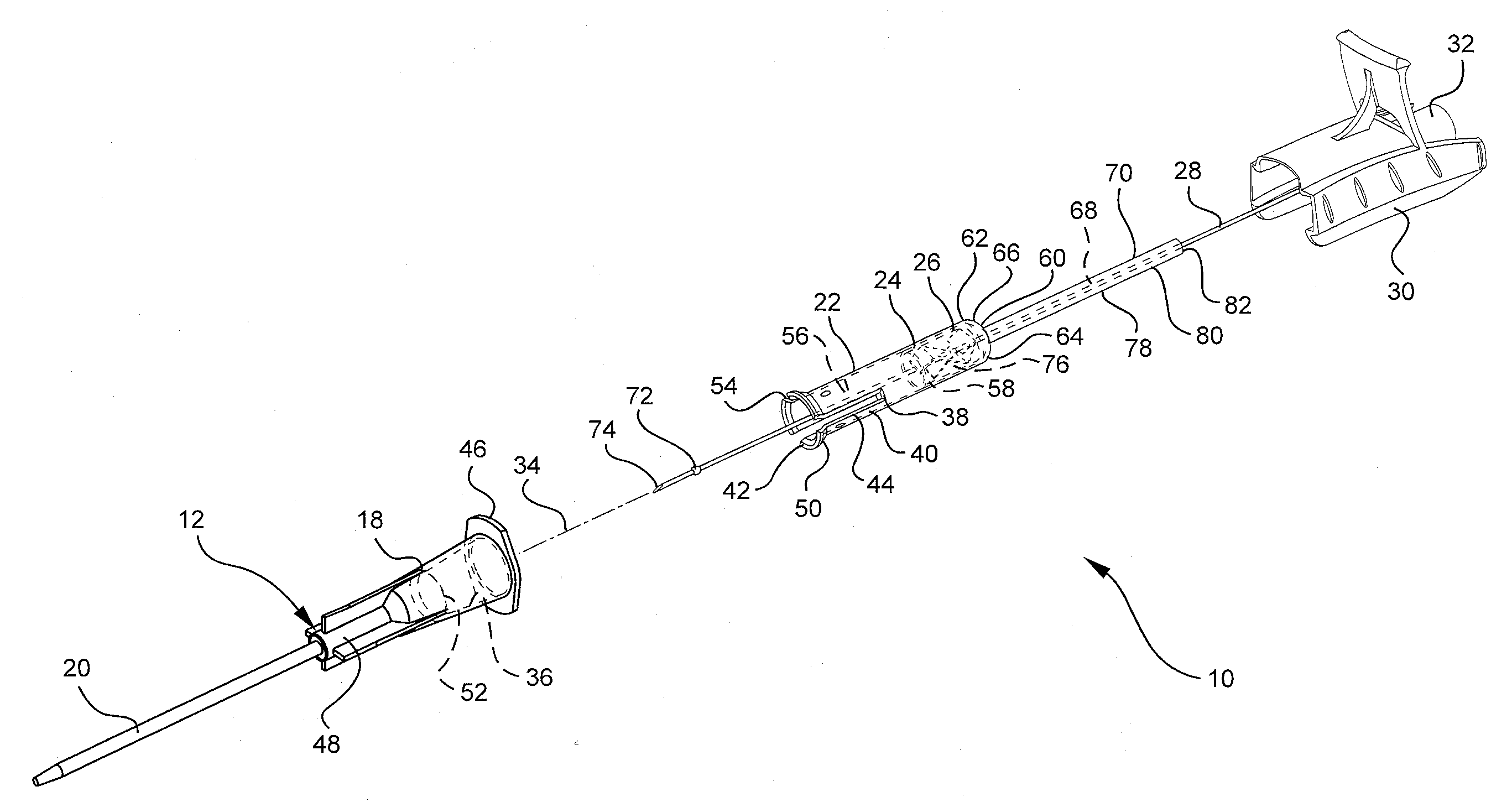
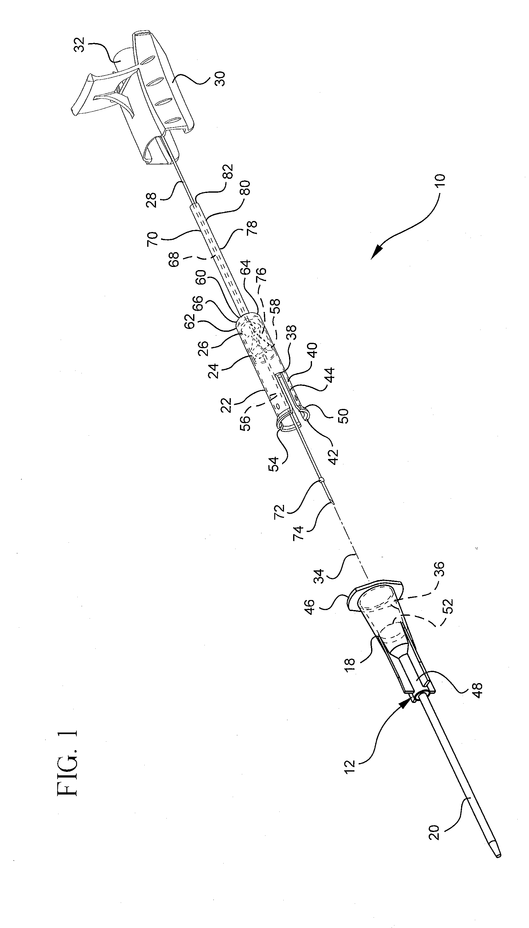
[0028]Referring to FIG. 1, a perspective view shows an example of a vascular access system 10. This example of a vascular access system 10 includes a catheter assembly 12, a needle shield assembly 14, and a needle assembly 16. The catheter assembly 12 includes a catheter adapter housing 18 and a catheter 20. The needle shield assembly 14 includes an o...


PUM


Abstract

A needle shield system may include a needle, an inner tube, a clip within the inner tube, an outer tube, and/or a housing. A method of shielding a needle may include housing a portion of a needle within a clip, housing the clip within an inner tube, housing the inner tube within an outer tube, housing the outer tube within a housing, interlocking the outer tube and the housing, withdrawing the needle from the clip, trapping a tip of the needle between the clip and the inner tube, partially withdrawing the inner tube from the outer tube, and/or releasing the outer tube and the housing from each other.

Description

BACKGROUND OF THE INVENTION[0001]This disclosure relates generally to vascular access devices and methods, including hypodermic needles, catheter assemblies, and devices used with catheter assemblies. Generally, vascular access devices are used for communicating fluid with the vascular system of patients. For example, catheters are used for infusing fluid, such as saline solution, various medicaments, and / or total parenteral nutrition, into a patient, withdrawing blood from a patient, and / or monitoring various parameters of the patient's vascular system.[0002]Intravenous (IV) catheter assemblies are among the various types of vascular access devices and over-the-needle peripheral IV catheters are a common IV catheter configuration. As its name implies, an over-the-needle catheter is mounted over an introducer needle having a sharp distal tip. The introducer needle is generally a hypodermic needle coupled to a needle assembly to help guide the needle and to facilitate its cooperation...

Claims


Application Information

Patent Timeline
Patent Type & Authority Applications(United States)
IPC IPC(8): A61M5/32
CPCA61M5/3273A61M2005/325A61M25/0618A61M25/0606
Inventor BRIMHALL, GREG L.
Owner BECTON DICKINSON & CO
Why Eureka
Try Eureka