Current limiting circuit breaker

A circuit breaker and circuit technology, which is applied to circuit breaker components, circuits, circuit devices, etc., can solve the problems of high cost, large power consumption of refrigerators, and unestablished practical application, and achieve the goal of improving current limiting performance and reducing costs Effect

Inactive Publication Date: 2009-08-12
Y Y L
View PDF8 Cites 20 Cited by
  • Summary
  • Abstract
  • Description
  • Claims
  • Application Information

AI Technical Summary

Problems solved by technology

[0020] Although this method has the characteristics that the current-limiting circuit breaker is an active current-limiting circuit breaker that operates at high speed and does not need to perform fault detection, but because of the large power consumption and high cost of the refrigerator used to maintain the superconducting state, Therefore, no practical target has been established at this stage

Method used


Image

  • Current limiting circuit breaker
  • Current limiting circuit breaker
  • Current limiting circuit breaker

Examples


Embodiment approach 1

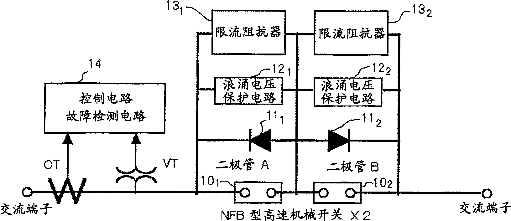
[0104] figure 1 , is a diagram showing the configuration of one embodiment of the present invention. If yes figure 1 For reference, this embodiment is a composite semiconductor current-limiting circuit breaker using both semiconductor devices and mechanical switches. Connect high-speed mechanical switches in series (10 1 、10 2 ), and at high speed mechanical switches (10 1 、10 2 ), connect diodes in parallel (11 1 、11 2 ), surge voltage protection circuit (12 1 、12 2 ), current limiting resistor (13 1 、13 2 ). Diode (11 1 、11 2 ) anodes are connected to each other, and the anode connection point is connected to the connection point of the high-speed mechanical switch. Although not particularly limited, in this embodiment, the high-speed mechanical switch (10 1 、10 2 ), respectively composed of NFB type high-speed mechanical switches.

[0105] figure 1 This embodiment of the Figure 8 The composition of is different in the following aspects.

[0106] High...

Embodiment approach 2

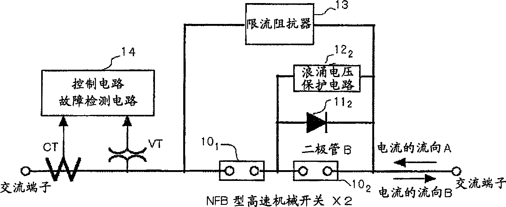
[0122] figure 2 , is a diagram showing the configuration of the second embodiment of the present invention. If refer to figure 2 , then only relative to the high-speed mechanical switch 10 2 And set the diode B (11 2 ). Although not particularly limited, in this embodiment, the high-speed mechanical switch (10 1 、10 2 ), respectively composed of NFB type high-speed mechanical switches.

[0123] The operation of the second embodiment will be described. Normally, current flows through a high-speed mechanical switch 10 1 、10 2 , while in diode B(11 2 ) There is no current flow (or leakage current). ie, with figure 1 The same as the first embodiment.

[0124] If a fault current is detected, 2 high-speed mechanical switches 10 1 、10 2 In the ON state, an arc plasma is generated between the electrodes of the high-speed mechanical switch. When the flow direction of the current at this moment is the B direction, the current flows to the diode B (11 2 ) commutation, ...

Embodiment approach 3

[0128] shown in figure 2 The example, high-speed mechanical switch 10 1 、10 2 connected in series, for high-speed mechanical switches 10 1 Since no diode is connected, it can be a circuit that can be completely disconnected. This is shown as a third embodiment in image 3 .

[0129] shown in image 3 In the composition, at normal runtime, with figure 1 , figure 2 same. If a fault current is detected, the high-speed mechanical switch 10 1 、10 2 becomes on. Then, arc plasma is generated between the electrodes. Moreover, if the flow of the current is in the B direction, the current flows to the diode B (11 2 ) commutation. When reversed, wait half a cycle. Then, the arc plasma between the electrodes of the high-speed mechanical switch is extinguished, and the current flows through the current-limiting resistor 13 2 , start current limiting. Although not particularly limited, in this embodiment, the high-speed mechanical switch (10 1 、10 2 ), respectively compos...


PUM


Abstract

To provide a current limiting circuit breaker capable of achieving downsizing and cost reduction of a device while improving current limiting performance. The current limiting breaker is provided with a first and a second mechanical switch (10, 10) connected in series, a first diode (11), a first snubber circuit (12), and a first current limiting impedance (13) which are mutually connected in parallel between both ends of the first mechanical switch, and a second diode (11), a second snubber circuit (12), and a second current limiting impedance (13) which are mutually connected in parallel between the both ends of the second mechanical switch. The anodes of the first and the second diodes are connected to each other and connected to the connection point of the first and the second mechanical switches.

Description

technical field [0001] The present invention relates to circuit breakers. Background technique [0002] Current-limiting circuit breakers that suppress the current when the power system fails to a certain value can be divided into two types: active type and passive type. [0003] The passive type performs automatic detection and automatic recovery of fault current. The active type uses a sensor to make the current-limiting circuit breaker work through a control signal. [0004] Representative current-limiting circuit breakers include arc-driven types, semiconductor switch types, LC resonant types, and rectifier types that utilize superconductivity. In addition, although the purpose of the current limiting circuit breaker is to limit the current of the fault current, it is necessary to break the circuit in the end, and it is preferable to have a circuit breaking function. [0005] Figure 7 , is an example of an arc-driven current-limiting circuit breaker (Technical Report...

Claims


Application Information

Patent Timeline
Patent Type & Authority Applications(China)
IPC IPC(8): H02H9/02H01H9/30H01H73/18
CPCH01H33/59H01H71/1045H01H9/42H01H9/40H01H9/541H01H33/16
Inventor 山口作太郎
Owner Y Y L
Why Eureka
Try Eureka