
Air filter arrangement and method for manufacturing the same

An air filter and filter technology, applied in membrane filters, chemical instruments and methods, combined devices, etc., can solve the problems of reduced airflow through the filter, increased pressure drop of the barrier filter, etc., to avoid bending and reduce use. Longevity, simple and quick installation and removal

Active Publication Date: 2009-08-12
ZEHNDER GROUP NORDIC
View PDF1 Cites 14 Cited by
  • Summary
  • Abstract
  • Description
  • Claims
  • Application Information

AI Technical Summary

Problems solved by technology

At the same time, the pressure drop across the barrier filter also increases, which results in reduced airflow through the filter

Method used


Image

  • Air filter arrangement and method for manufacturing the same
  • Air filter arrangement and method for manufacturing the same
  • Air filter arrangement and method for manufacturing the same

Examples


Embodiment Construction

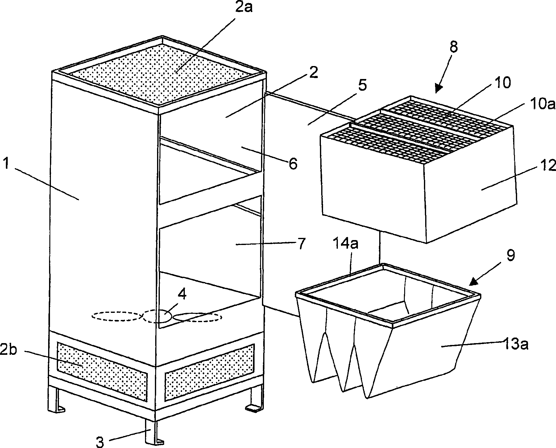
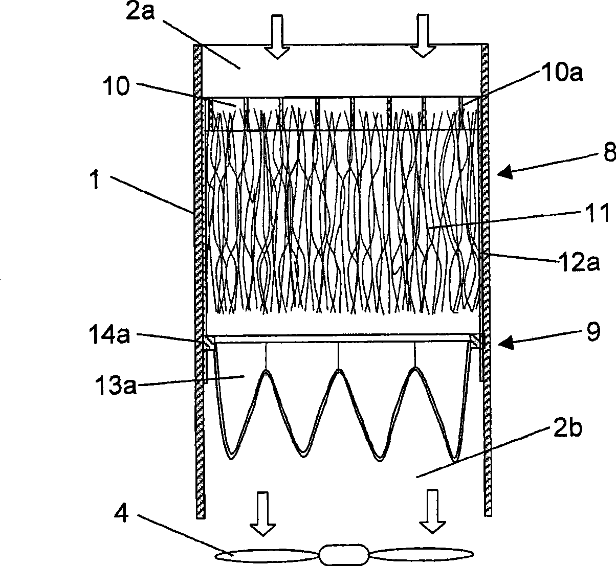
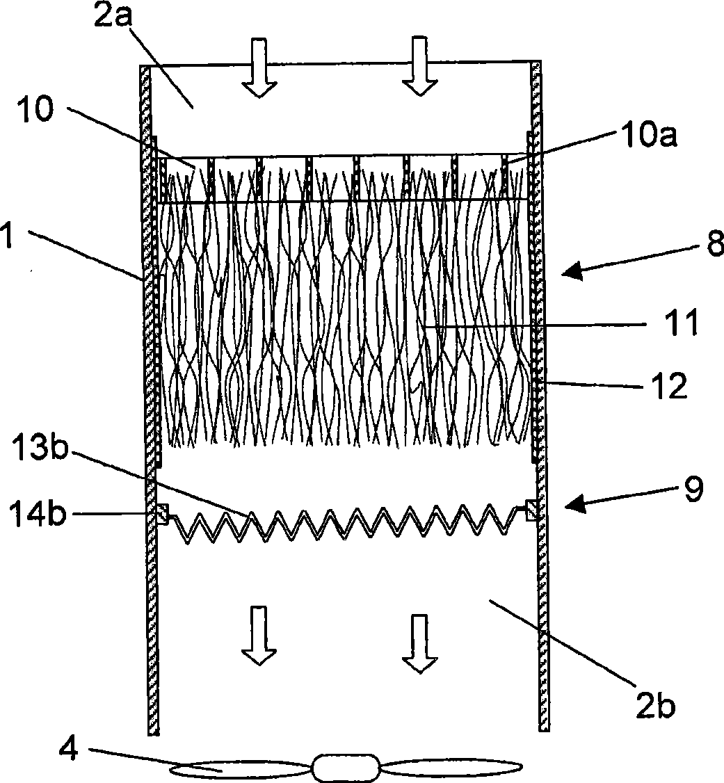
[0020] figure 1 The filter device is shown in the form of a wall element 1 delimiting an inner air channel 2 . In this case the filter device is provided with legs 3 so that it can be placed on a floor surface. Alternatively, it may be arranged in an elevated position and attached to a wall surface, top surface or similar. The air channel 2 has an air axial inlet 2a at the upper end of the filter device and a radial outlet 2b at the lower end of the filter device. The filter device comprises a uniform floor 1a which enables air to flow out of the filter device only through radial outlets 2b. The schematically shown fan 4 is suitable for achieving a forced air flow through the air channel 2 . The filter device comprises an openable cover 5 which seals the first opening 6 and the second opening 7 to the air channel 2 when the cover is in the closed position. When the cover 5 is in the open position, a first air filter 8 can be installed and removed from the air passage 2 thr...


PUM


Abstract

The present invention relates to an air filter arrangement and a method for manufacturing such air filter arrangement. The air filter arrangement comprises an air channel (2), a first air filter (8) mounted in the air channel (2), which first air filter comprises a filter frame (10) provided with at least one passage (10a) for through flow of air, and a filter body (11) comprising electrostatically chargeable fibres which are attached to the filter frame (10) such that the filter body (1 1) obtains an extension from the filter frame (10) to a position located at a distance from and downstream the filter frame (10) with respect to the flow direction of the air through the air channel (2). The air filter arrangement comprises a second air filter comprising a filter cloth which, in a mounted state, is adapted to extend across the air channel (2) such that it is flown through by air flowing in a substantial longitudinal direction in the air channel (2), and that the second airfilter is mounted in the air channel (2) in a position located downstream the first air filter (8) with respect to the flow direction of the air through the air channel (2).

Description

technical field [0001] The present invention relates to an air filter device and a method of manufacturing such an air filter device. Background technique [0002] The air filter device includes an air channel, a first air filter installed in the air channel, wherein the first air filter includes a filter frame and a filter body, the filter frame is provided with at least one filter for air flow channels, the filter body comprising electrostatically chargeable fibers attached to the filter frame such that the filter body achieves a predetermined flow direction from the filter frame to the air channel relative to the flow of air through the air channel at a distance from the filter frame An extension at a position some distance downstream. [0003] When air flows through a first air filter of the type described above, the fibers in the filter body have mutual movement so that they rub against each other. This friction and friction as the airflow passes through the fibers ke...

Claims


Application Information

Patent Timeline
Patent Type & Authority Applications(China)
IPC IPC(8): B03C3/017B01D50/00
CPCB03C3/09B01D46/0023B03C3/64B01D2273/30B01D46/0032B03C3/30B03C3/017Y10T29/49826B01D46/62B01D50/00
Inventor 斯塔凡·克兰茨
Owner ZEHNDER GROUP NORDIC
Learn More