
Electric supercharger

一种电动增压器、旋转驱动的技术,应用在发动机元件、发动机功能、燃烧发动机等方向,能够解决结构复杂、冷却效率差等问题

Active Publication Date: 2009-08-12
IHI CORP
View PDF3 Cites 10 Cited by
  • Summary
  • Abstract
  • Description
  • Claims
  • Application Information

AI Technical Summary

Problems solved by technology

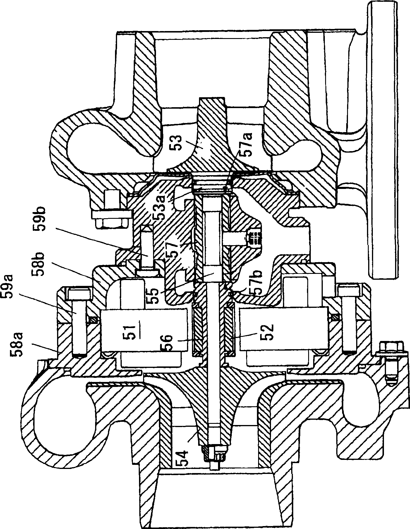
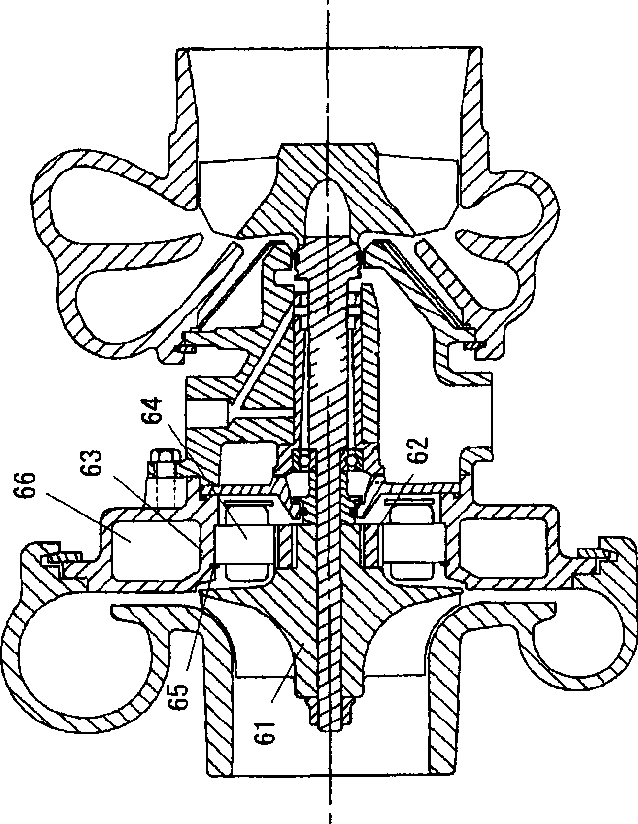
In addition, since the water cooling jacket 71a is provided in the wall portion of the central housing 71, it is necessary to form the water cooling jacket 71a of the central housing 71 with a casting or the like, resulting in a complicated structure.
And, since the electric motor box 76 is cooled not directly by the water cooling jacket 71a, but the electric motor box 76 is cooled via the wall portion of the central housing 71, the cooling efficiency is poor.

Method used


Image

  • Electric supercharger
  • Electric supercharger
  • Electric supercharger

Examples


Embodiment Construction

[0035] Hereinafter, preferred embodiments of the present invention will be described in detail based on the drawings. In addition, in each figure, the same code|symbol is attached|subjected to the common part, and repeated description is abbreviate|omitted.

[0036] Figure 4 It is an overall configuration diagram of the electric supercharger according to the first embodiment of the present invention. In this figure, the electric supercharger 10 of the present invention has a turbine shaft 12 , a compressor wheel 14 and a housing. In this embodiment, the housing consists of a bearing housing 16 , a turbine housing 18 and a compressor housing 20 .

[0037] The turbine shaft 12 has a turbine wheel 11 at one end (left end in the figure). In this example, the turbine wheel 11 is formed integrally with the turbine shaft 12 , but the present invention is not limited to this, and the turbine wheel 11 may be separately attached.

[0038] The compressor impeller 14 is integrally ro...


PUM


Abstract

An electric supercharger comprises a stator assembly (29) inserted into a bearing housing (16) and a seal plate (28) firmly stuck to the compressor side of the stator assembly (29) and partitioning a compressor housing (20) from a motor stator (24). The stator assembly (29) includes the motor stator (24) and an outer sleeve (26) the inner peripheral surface of which is firmly stuck to the outer peripheral surface of the motor stator (24) and which so supports the motor stator (24) as to restrain the rotation of the stator motor (24). The motor stator (24) and the outer sleeve (26) are formed as an integral part so as to constitute the stator assembly (29). The outer sleeve (26) constitutes a liquid-tight water-cooled jacket between itself and a bearing housing. The outer sleeve (26) and the seal plate (28) are axially tightened together between the bearing housing (16) and the compressor housing (20).

Description

technical field [0001] The present invention relates to an electric supercharger with a built-in electric motor. Background technique [0002] The process of supplying the air with increased density by the compressor to the engine is called supercharging, and the device that uses exhaust energy to maintain the driving work of the compressor is called an exhaust turbocharger. [0003] Generally, an exhaust turbocharger is composed of a compressor and a turbine arranged with a bearing unit interposed therebetween. The compressor has a compressor wheel built in, and the turbine has a turbine wheel built in. The compressor impeller and the turbine impeller are connected to each other by the connecting shaft (shaft) supported by the bearing unit, the exhaust gas of the engine is used to rotate the turbine impeller, and the driving force is transmitted to the compressor impeller through the connecting shaft, and the compressor impeller compresses air to boost the engine. [0004...

Claims


Application Information

Patent Timeline
Patent Type & Authority Applications(China)
IPC IPC(8): F02B39/00F02B37/10
CPCF02B39/10F05D2220/76F05D2230/60F01D25/14F01D15/10Y02T10/144F02B39/005F01D25/24F02B37/025F02B37/10F02C6/12F05D2220/40F01D25/12F05D2260/232Y02T10/12F02B37/04F02B39/02
Inventor 清水政宏渋井康行
Owner IHI CORP
Learn More