Film spray no-back mixing column plate

A technology of mixing towers and spray hoods, which is applied in the field of membrane spraying non-return mixing trays, can solve the problems of unfavorable trays and reduce the driving force of gas-liquid mass transfer, so as to avoid liquid back mixing, improve the driving force of mass transfer and tower The effect of plate efficiency

Active Publication Date: 2010-12-29
TIANJIN CHUANGJU TECHNOLGOY +1
View PDF7 Cites 0 Cited by
  • Summary
  • Abstract
  • Description
  • Claims
  • Application Information

AI Technical Summary

Problems solved by technology

But this combined element falls back on the tray due to the liquid ejected from the ejection hood, and the liquid that completes the gas-liquid mass transfer remixes with the liquid on the tray (i.e. back mixing), and then is sucked and lifted by the cap, reducing the The impetus of gas-liquid mass transfer is reduced, which is not conducive to the efficiency of the tray

Method used


Image

  • Film spray no-back mixing column plate
  • Film spray no-back mixing column plate
  • Film spray no-back mixing column plate

Examples


Embodiment Construction

[0011] Further describe the present invention below in conjunction with embodiment and accompanying drawing thereof:

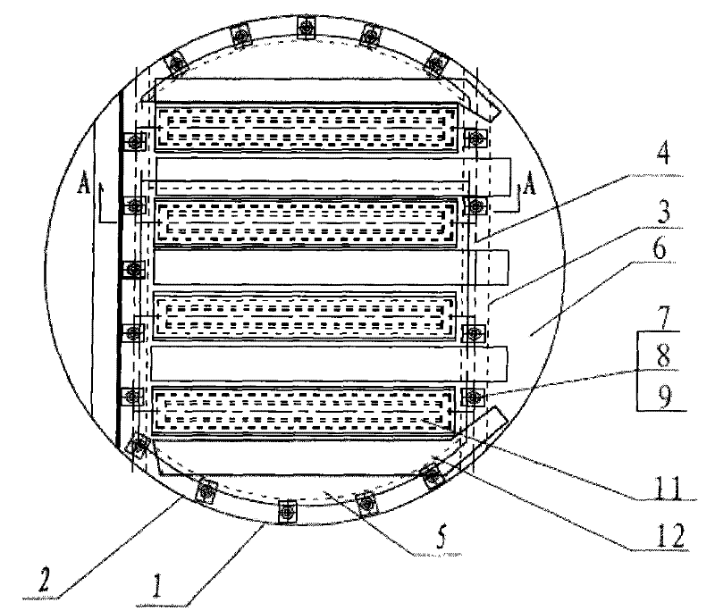
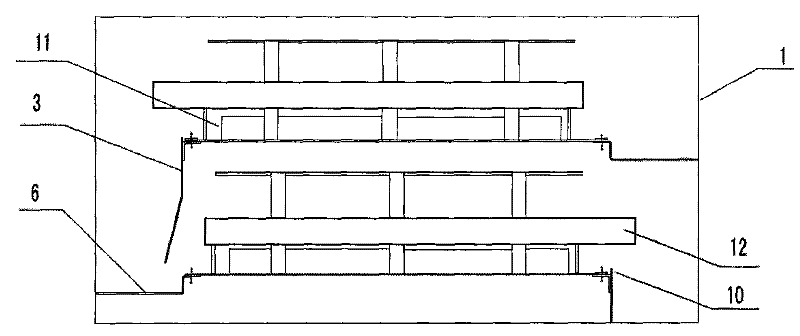
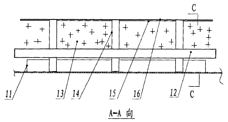
[0012] The film spraying of the present invention design has no back-mixing tray (abbreviation tray, see Figure 1-4 ), horizontally installed in the tower shell 1, including the spray cover, the tray ring 2 and the downcomer plate 3, the tray 5 is provided with air holes and the air riser 11 is installed, and the downcomer plate 3 and the tray 5 are formed The downcomer 6 is fixed with the top cover 16 through the support plate 14 at the position corresponding to the air hole of the tray 5, and there is a gap between the bottom of the spray cover and the tray 5, and the gap forms a passage for the liquid to enter the spray cover. The two side walls of the spray cover are provided with spray holes 13, which are characterized in that the gas rise holes on the tray 5 are rectangular, and the gas rise holes are welded with a rectangular gas riser 11, the gas rise...


PUM


Abstract

The invention relates to a film spray non-back-mixing column plate, which comprises two spray covers, a column tray ring and a down-flow plate. A column plate is provided with a raise steam hole, and a down-flow pipe is formed between the down-flow plate and the column plate, wherein a position opposite to the raise steam hole of the column plate is fixedly provided with a top cover through a supporting plate. The bottoms of the spray covers and the column plate are reserved with a gap which forms a channel for liquid to enter the spray cover, and both side walls of the spray covers are provided with spray holes. The film spray non-back-mixing column plate is characterized in that the raise steam hole on the column plate is rectangular, and the part of the raise steam hole is welded with a rectangular raise steam pipe, wherein the upper end of the raise steam pipe is provided with a nozzle; the top cover, the raise steam pipe and the supporting plate form the spray covers; and the space between the two spray covers and the outside of the edges of the spray covers are provided with a liquid guide groove, wherein three surfaces of the liquid guide groove are provided with walls, andone surface of the liquid guide groove is provided with an opening which extends into the down-flow pipe. The film spray non-back-mixing column plate can prevent the liquid from back mixing, and greatly improve mass transfer driving force and the column plate efficiency.

Description

technical field [0001] The invention relates to a column technology for separating chemical reaction and product, in particular to a jet tray used for distillation, absorption, desorption, humidification and heat exchange in the chemical industry, especially a membrane jet non-backmixing tray. Background technique [0002] Patent document ZL9920012.6 discloses a three-dimensional spray gas-liquid contact combination element. The feature of the combination element is that a support plate with a fixed height is left on the bottom edge of the cap, and a fixed bottom gap is formed between the side plate of the cap and the column plate. The combined element is used on the tray column, which can improve the processing capacity of the column equipment, reduce the pressure drop of the tray, improve the operation flexibility and mass transfer efficiency, and reduce the production cost. But this combined element falls back on the tray due to the liquid ejected from the ejection hood,...

Claims


Application Information

Patent Timeline
Patent Type & Authority Patents(China)
IPC IPC(8): B01D3/18B01D3/20B01D53/18
Inventor 王柱祥商恩霞宋洪涛
Owner TIANJIN CHUANGJU TECHNOLGOY
Why Eureka
Try Eureka