

Air-pressure electric-control auxiliary brake device
An auxiliary braking and electronic control technology, applied in the field of traffic safety, can solve the problems of inability to meet the requirements of safe driving assistance systems and vehicle active braking, and achieve the effects of simple structure, fast response speed and convenient installation.
- Summary
- Abstract
- Description
- Claims
- Application Information
AI Technical Summary
Problems solved by technology
Method used
Image

Examples
Embodiment Construction
[0011] The present invention will be described in detail below in conjunction with the accompanying drawings and embodiments.
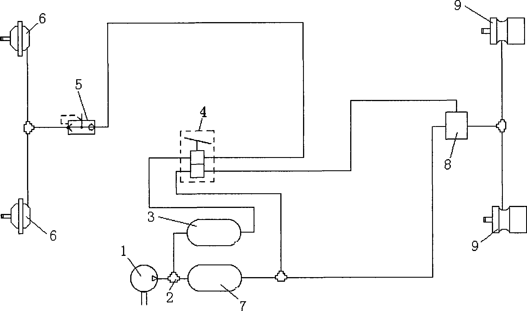
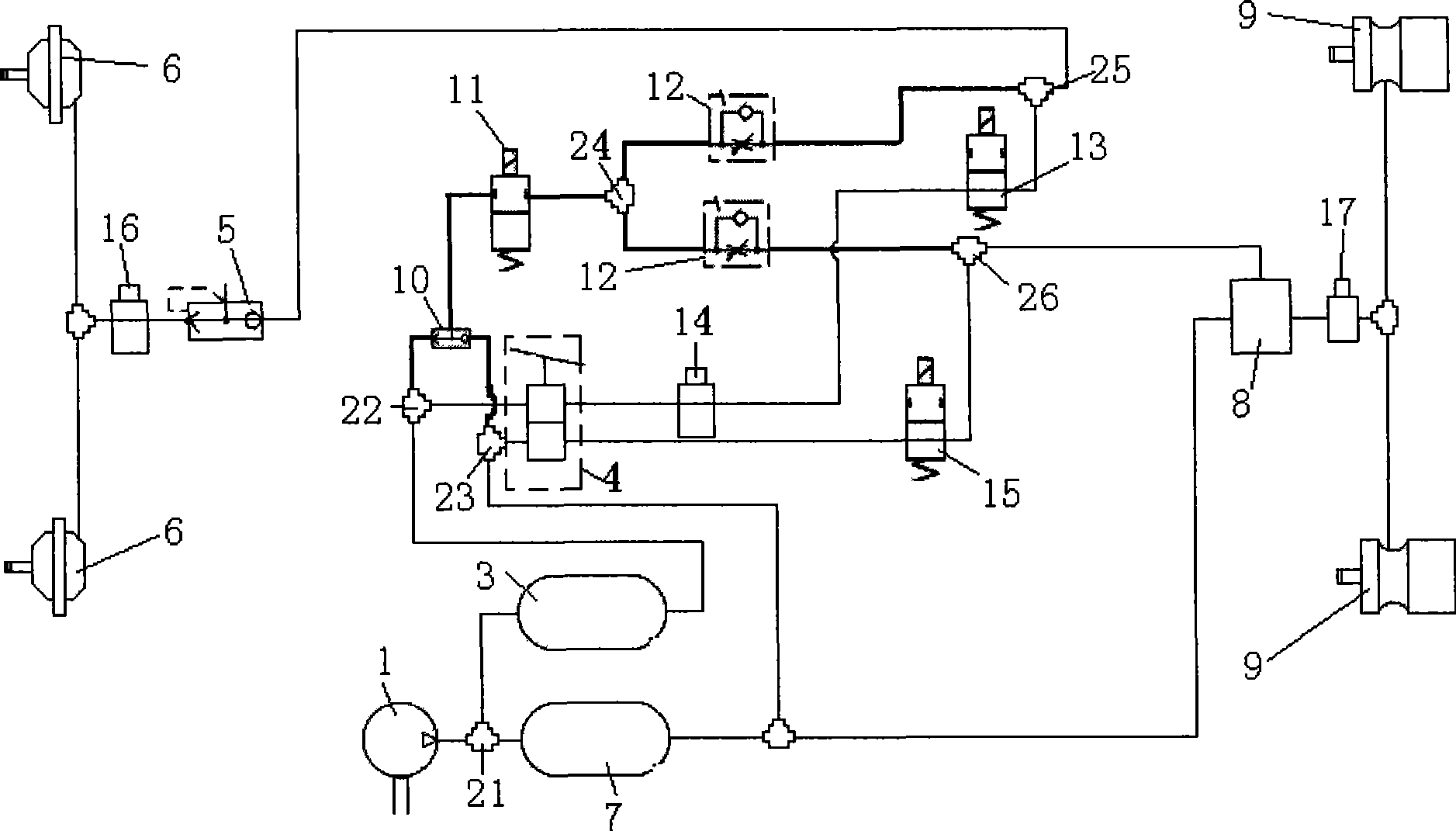
[0012] The device of the present invention adds a plurality of high-sensitivity high-speed on-off valves, a plurality of pressure sensors, a plurality of one-way valves, a shuttle valve and a plurality of three-way valves on the basis of the original vehicle braking system, and the controller on the vehicle (Fig. (not shown in ) calculates and judges that the vehicle is currently in danger of rear-end collision, it collects the pressure signal detected by the pressure sensor, and controls the high-speed switching valve according to the pressure signal, so that the braking circuit of the device of the present invention has manual braking and electronic control. There are two switchable working modes for braking.
[0013] Among them, the braking circuit of the manual braking mode is the braking circuit of the original vehicle braking system (abbreviated...
PUM
 Abstract
Description
Claims
Application Information