Automatic conveying apparatus for parts

An automatic conveying device and parts technology, which is applied in conveyor control devices, vibrating conveyors, conveyors, etc., can solve the problems of high parts rejection rate, prone to accidents, low parts conveying efficiency, etc. The effect of high conveying efficiency and low labor cost

Active Publication Date: 2009-08-19
广州市新豪精密科技有限公司
View PDF0 Cites 29 Cited by
  • Summary
  • Abstract
  • Description
  • Claims
  • Application Information

AI Technical Summary

Problems solved by technology

The existing thread rolling machine for processing external threads of parts, the conveyance of the processed parts is carried out manually, and the parts are inserted into the cutters of the thread rolling machine one by one by hand to complete the thread processing. Not only the part conveying efficiency is low, but also special Arrange delivery personnel, high labor cost
In addition, after repeating the same part delivery operation for a long time, the energy and concentration of the delivery personnel will decrease, which is prone to accidents and poses safety hazards
In addition, there are certain requirements for the insertion length and insertion force of the parts when the thread rolling machine is processing the thread. If the insertion length or force is too large or too small, the quality of the thread will be affected. In order to ensure the processing quality, the feeding personnel must strictly control it during the processing. The insertion depth and strength of the parts have high requirements for the feeding personnel, and the feeding personnel usually rely on experience, which cannot guarantee that the insertion depth and strength of each part meet the requirements, so the scrap rate of the processed parts is high.

Method used


Image

  • Automatic conveying apparatus for parts

Examples


Embodiment Construction

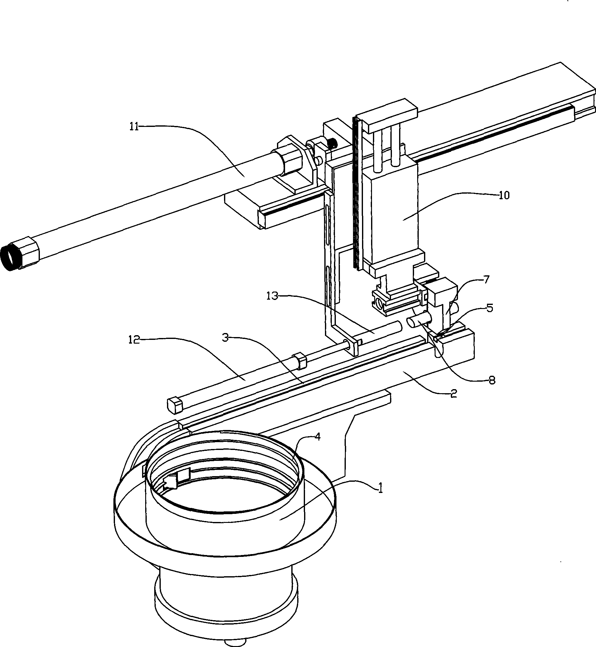
[0007] A parts automatic conveying device, such as figure 1 , including a vibrating plate 1 and a vibrating groove 2, a groove 3 for conveying parts on the vibrating groove is connected to the outlet end of the conveying groove 4 spirally arranged on the vibrating plate, and the end of the vibrating groove is equipped with a manipulator 7 capable of clamping workpieces, The manipulator is installed on the No. 1 cylinder 10, and the No. 1 cylinder is installed on the No. 2 cylinder 11. The manipulator can be driven to move up and down in the vertical direction and move back and forth in the horizontal direction through the No. 1 cylinder and the No. 2 cylinder. The automatic parts delivery device also includes three No. 12 cylinder, No. 3 cylinder front end is installed with a push block 13 that moves back and forth. The position of the push block is opposite to the feed port of the processing equipment. in place. The manipulator can be a device capable of clamping parts from ...


PUM


Abstract

The invention discloses an automatic conveying device for parts. A groove for conveying the parts on a vibrating groove is connected with the outlet end of a conveying groove spirally arranged on a vibrating disc, the tail end of the vibrating groove is provided with a manipulator for clamping a workpiece, the manipulator is arranged on a first cylinder which is arranged on a second cylinder, the manipulator is moved in the vertical direction and the horizontal direction by driving the first cylinder and the second cylinder, the automatic conveying device for the parts also comprises a third cylinder, the front end of the third cylinder is provided with a pushing block for pushing the third cylinder to move forwards and backwards, and the position of the pushing block is opposite to a feed opening of a processing device. The automatic conveying device can automatically finish the conveying process of the parts, has high conveying efficiency, does not need a special personnel, reduces the manpower cost, can accurately control the inserting depth and the force through the pushing block driven by the cylinder to push the parts to be inserted into the processing device, and can reduce the defective index of the processed parts.

Description

technical field [0001] The invention relates to a device capable of automatically conveying parts. technical background [0002] In order to improve production efficiency and meet the needs of mass production, the degree of automation of processing equipment should be improved as much as possible during the processing of mechanical parts. The existing thread rolling machine for processing external threads of parts, the conveyance of the processed parts is carried out manually, and the parts are inserted into the cutters of the thread rolling machine one by one by hand to complete the thread processing. Not only the part conveying efficiency is low, but also special Arranging material delivery personnel, the input cost is high. In addition, after repeating the same part delivery operation for a long time, the energy and concentration of the delivery personnel will decrease, which is prone to accidents and poses safety hazards. In addition, there are certain requirements for...

Claims


Application Information

Patent Timeline
Patent Type & Authority Applications(China)
IPC IPC(8): B65G27/02B65G47/34B65G47/90B65G43/08B23G11/00B21H9/00
Inventor 雷廷勇黄振钦邱雪锋
Owner 广州市新豪精密科技有限公司
Why Eureka
Try Eureka