Particulate floatation device

A flotation device and particle technology, which is applied in the direction of flotation water/sewage treatment, etc., can solve the problems of increased equipment use, high energy consumption, short service life, etc., to save product cost, save connection pipes, and reduce energy consumption Effect

Inactive Publication Date: 2009-08-19
重庆市水产科学研究所
View PDF0 Cites 0 Cited by
  • Summary
  • Abstract
  • Description
  • Claims
  • Application Information

AI Technical Summary

Problems solved by technology

The deficiencies of the existing dissolved air flotation machines are: (1) Dissolved air pumps, dissolved air tanks or dissolved air pipes are required in the process of dissolving the air. Most of these equipment are imported, the price is high, and the energy consumption is large during use; (2) In order to fully float the suspended particles, the height of the ordinary air flotation tank is relatively large and takes up a lot of space. A rotati

Method used


Image

  • Particulate floatation device
  • Particulate floatation device
  • Particulate floatation device

Examples


Embodiment Construction

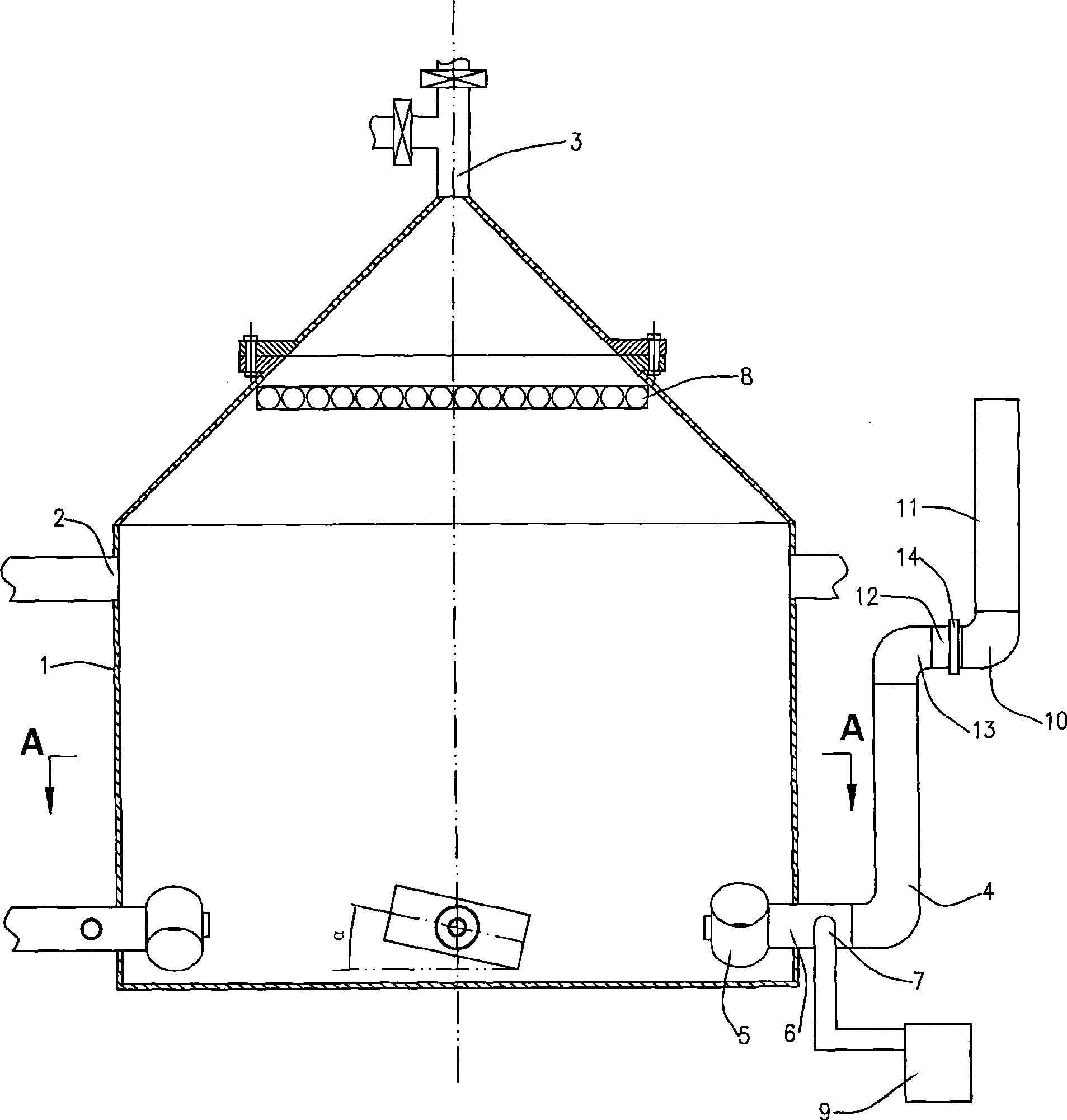
[0020] figure 1 , 2 As shown, the particle flotation device of the present invention is made of tank body 1, Roots blower 9, gas-liquid mixing device, multifaceted hollow ball 8 and clear water drain pipe, the bottom of tank body 1 is barrel-shaped, and the top is conical, The upper and lower ends of the barrel-shaped part are respectively provided with a sewage water inlet 2 and a clear water discharge outlet, and a slag discharge port 3 is provided at the sharp corner of the conical part, and a valve is installed at the slag discharge port 3, and the slag discharge port is passed through the slag discharge port. 3 Discharge slag outward.

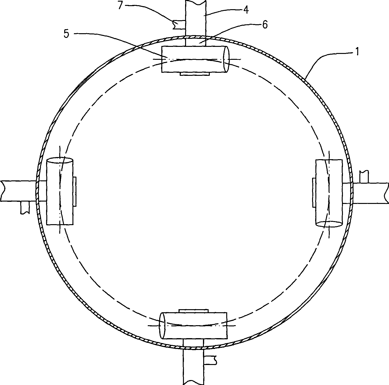
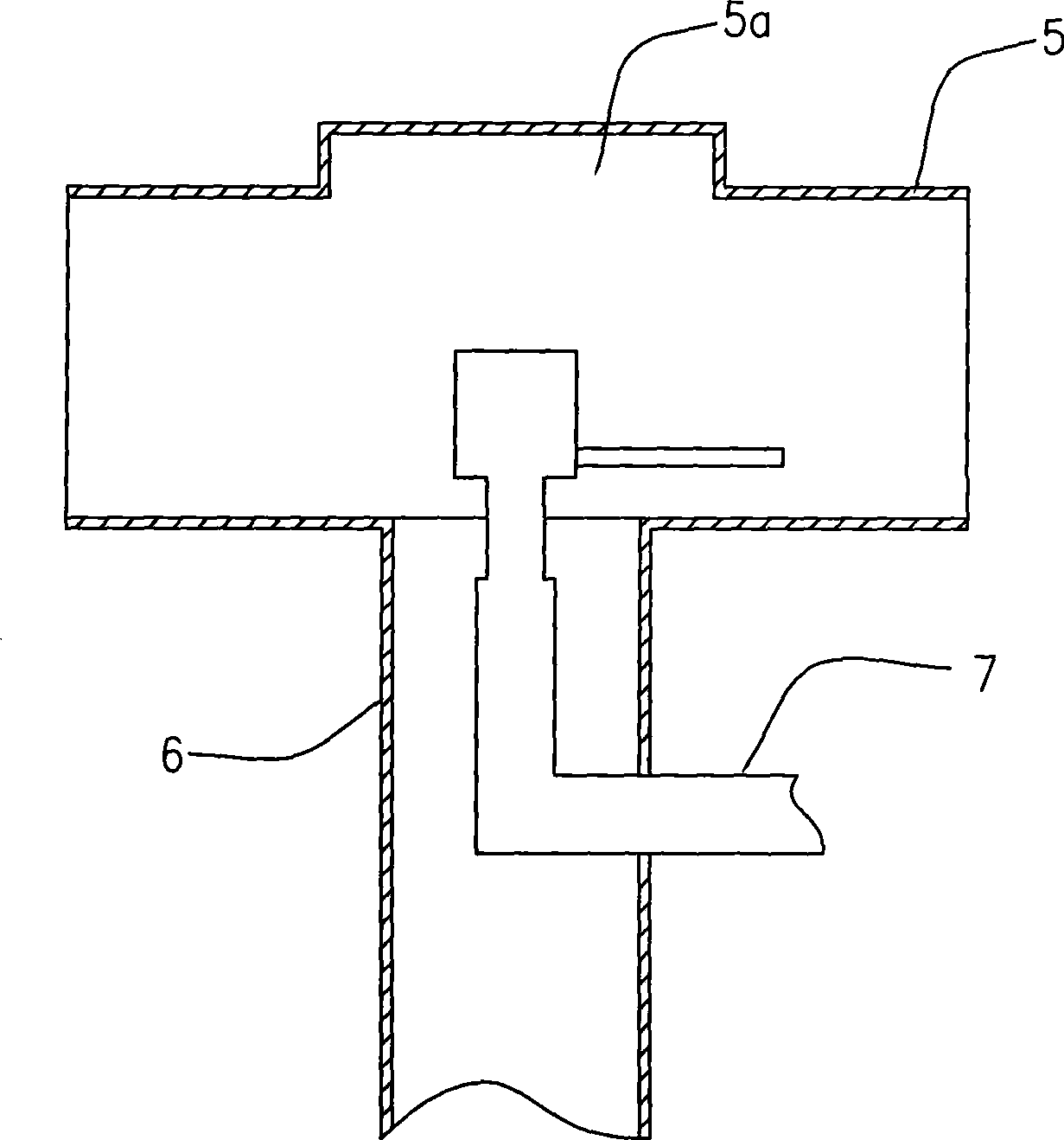
[0021] figure 2 It is shown that two pairs of gas-liquid mixing devices are radially symmetrically arranged at the inner bottom of the tank body 1, see further image 3 , 4 , each gas-liquid mixing device is composed of a gas-liquid mixing pipe 5, a drain pipe 6 and an air inlet pipe 7, wherein the gas-liquid mixing pipe 5 is vertical...


PUM


Abstract

The invention discloses a particle flotator, which comprises a cylindrical tank and an air blower, wherein the tank is provided with a sewage inlet, a clear water outlet and a slag outlet; the inner bottom part of the tank is symmetrically provided with one to four pairs of gas-liquid mixing devices along the radial direction, and each gas-liquid mixing device consists of a gas-liquid mixing pipe, a water outlet pipe and a gas inlet pipe, wherein the gas-liquid mixing pipe and the water outlet pipe are vertically connected and communicated; the axis line of each gas-liquid mixing pipe is tangent to the same circle, and the circle and a circle in which the tank is positioned are concentric circles; and the other end of the water outlet pipe is extended out of the clear water outlet, the water outlet pipe is provided with the gas inlet pipe, and one end of the gas inlet pipe is extended in the gas-liquid mixing pipe, while the other end is extended out of the water outlet pipe and connected with an air outlet of the air blower. The particle flotator directly acts on water in the tank, and the independent air dissolved process is not needed, thereby unnecessarily using a high-priced air dissolved tank or air dissolved pipe, greatly saving connecting pipes, valves and associated facilities, and greatly saving product cost and lowering energy consumption.

Description

technical field [0001] The invention relates to a water treatment device, in particular to a particle flotation device for water treatment using air flotation technology. Background technique [0002] Dissolved air flotation is a kind of air flotation. It uses the characteristics of different solubility of water under different pressures to pressurize and add air to all or part of the water to be treated (or treated) to increase the amount of air dissolved in water. Pour into water with coagulant added, release under normal pressure, air precipitates to form small bubbles, which adhere to impurity flocs, causing the overall density of flocs to be lower than that of water to rise, thereby separating solid and liquid. The existing air flotation machine is mainly composed of blower, high-pressure pump, dissolved air tank, air releaser, air flotation pool, slag removal equipment, etc. Its working principle is: air fully contacts with water in the dissolved air tank under pressur...

Claims


Application Information

Patent Timeline
IPC IPC(8): C02F1/24
Inventor 胡重江吴立敏胡春霞
Owner 重庆市水产科学研究所
Why Eureka
Try Eureka