
Liquid crystal spraying apparatus

A spraying device, liquid crystal technology, applied in nonlinear optics, instruments, optics, etc., to achieve the effect of improving process efficiency

Active Publication Date: 2009-08-19
AU OPTRONICS CORP
View PDF0 Cites 10 Cited by
  • Summary
  • Abstract
  • Description
  • Claims
  • Application Information

AI Technical Summary

Problems solved by technology

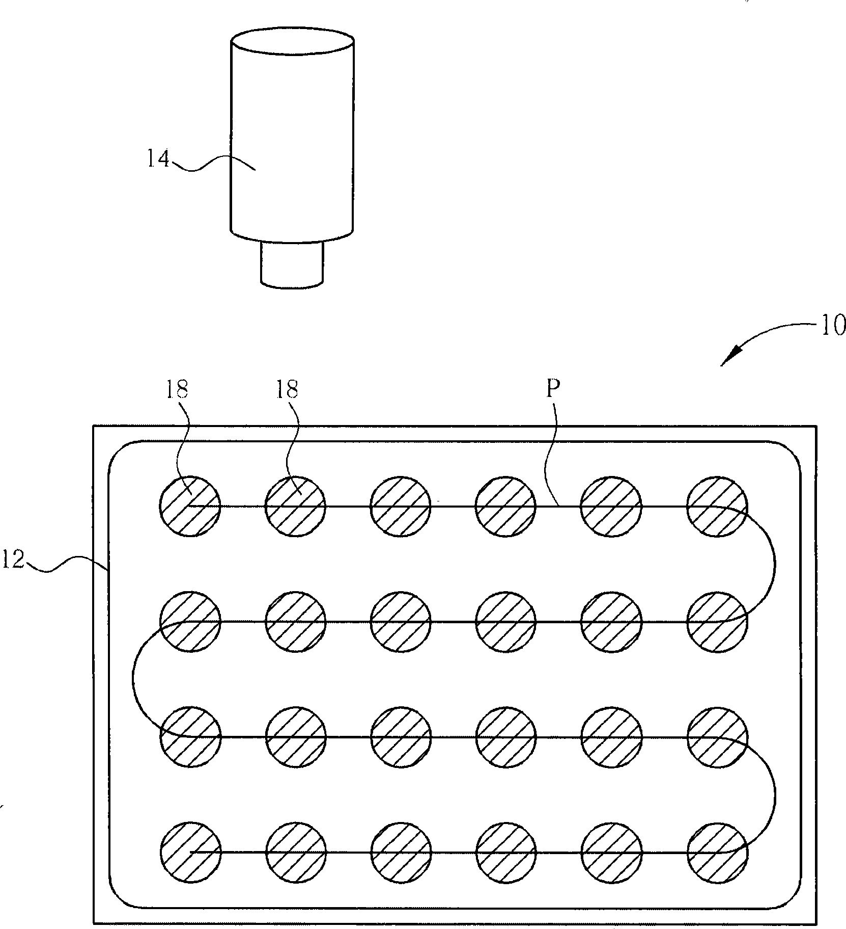
[0005] One of the purposes of the present invention is to provide a liquid crystal display panel to solve the aforementioned existing problems, so as to improve the process efficiency of the liquid crystal dropping process

Method used


Image

  • Liquid crystal spraying apparatus
  • Liquid crystal spraying apparatus
  • Liquid crystal spraying apparatus

Examples


Embodiment Construction

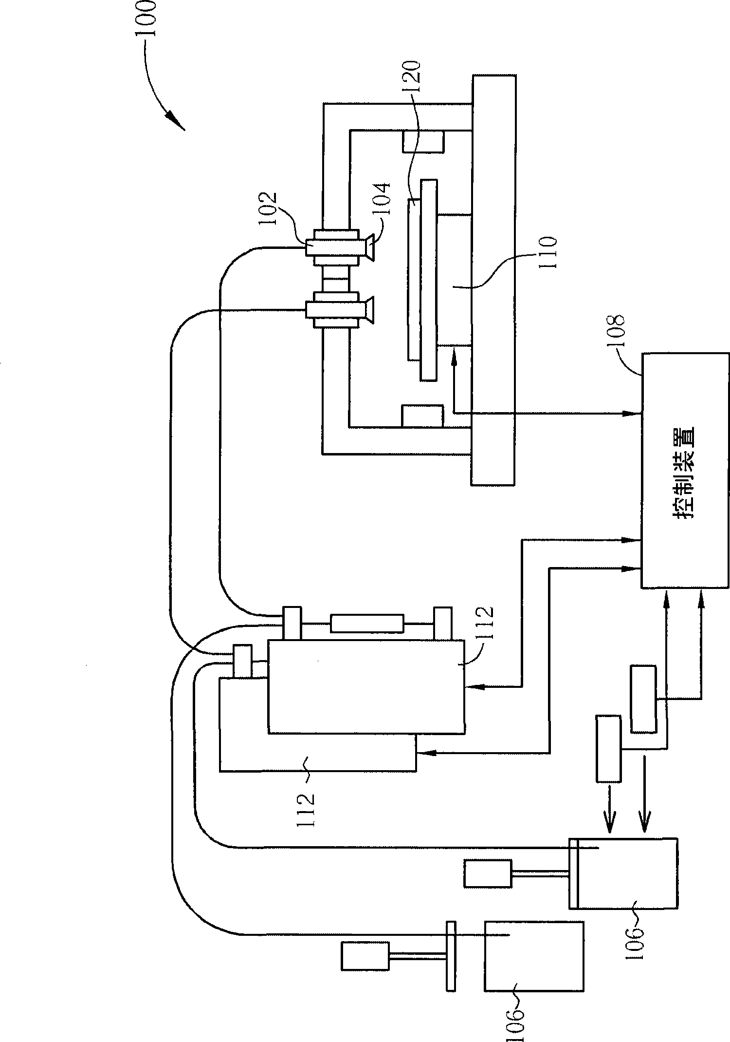
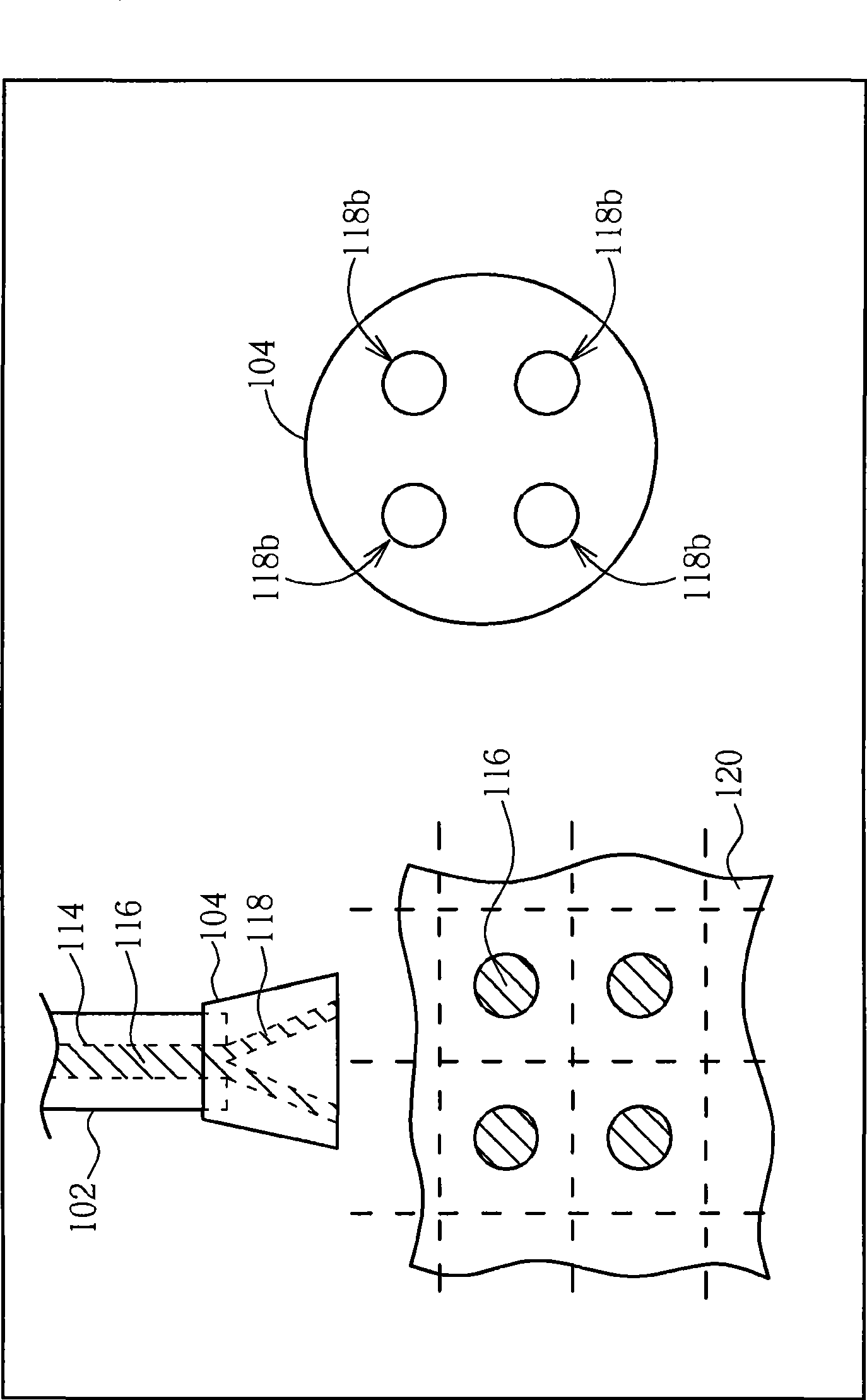
[0028] In order to enable those skilled in the technical field of the present invention to further understand the present invention, a number of preferred embodiments of the present invention are enumerated below, together with the accompanying drawings, to describe in detail the composition and desired effects of the present invention.

[0029] Please refer to Figure 2 to Figure 4 . Figure 2 to Figure 4 Shown is the schematic diagram of the liquid crystal spraying device of a preferred embodiment of the present invention, wherein figure 2 It is a schematic diagram of the liquid crystal dropping process using a liquid crystal spraying device, image 3 is a partially enlarged schematic diagram of the liquid crystal spraying device, and Figure 4 A schematic perspective view of a sprinkler head. Wherein, the same components or parts are represented by the same symbols. It should be noted that the drawings are for illustration purposes only and are not drawn to original sc...


PUM


Abstract

The invention relates to a liquid crystal spraying device used for improving the efficiency of liquid crystal dripping. The liquid crystal spraying device contains a dripping device and a spray head. The dripping device is provided with a distribution pipe which is used for conveying liquid crystal materials. The spray head is installed on the bottom of the dripping device and connected the distribution pipe, and is provided with a plurality of spraying flow channels, wherein, each spraying flow channel is respectively and directly communicated to the distribution pipe. By the invention, the technical efficiency of the liquid crystal dripping technique can be greatly improved. Besides, as the invention utilizes non-bending straight spraying flow channels for spraying liquid crystal drops, the liquid crystal materials are not easy to be blocked at the bending point and can be evenly distributed to each spraying flow channel, and the phenomenon that the sizes of the sprayed liquid crystal drops are different, which is caused by the excess difference.of the shape and the length of the all the spraying flow channels, is not easy to occur.

Description

technical field [0001] The invention relates to a liquid crystal spraying device, in particular to a liquid crystal spraying device which uses a spraying head to drop a plurality of liquid crystal drops at a time. Background technique [0002] The liquid crystal display panel includes a color filter substrate (color filter substrate, CF substrate), a thin-film transistor substrate (thin-film transistor substrate, TFT substrate), and a layer of liquid crystal molecules filled between the CF substrate and the TFT substrate. The liquid crystal display panel can be roughly divided into two types according to the filling method of liquid crystal molecules: vacuum injection and one drop fill (ODF). Vacuum injection refers to bonding the CF substrate and the TFT substrate first and leaving a small hole on the side of the CF substrate and the TFT substrate, and then using the capillary principle to slowly inject liquid crystal molecules between the CF substrate and the TFT substrate...

Claims


Application Information

Patent Timeline
IPC IPC(8): G02F1/1341
Inventor 石坤城林俊杰吴成益郭融徐盟贵
Owner AU OPTRONICS CORP
Learn More