
Front maintenance type back casting large screen display unit capable of remote control adjusting light path

A display unit and front maintenance technology, applied in electrical components, TV, color TV components and other directions, can solve the problem of time-consuming and laborious running back and forth, failing to achieve the effect, affecting the display area of ​​the display wall, etc. The effect of maintaining the space behind

Inactive Publication Date: 2011-08-10
SHANGHAI LINBELL ELECTRONICS TECH
View PDF0 Cites 0 Cited by
  • Summary
  • Abstract
  • Description
  • Claims
  • Application Information

AI Technical Summary

Problems solved by technology

Display units using this technology can only achieve stacking of no more than two layers in the application of display wall splicing, which will affect the display area of ​​the display wall
Moreover, the display wall spliced ​​into the second floor will occupy the space on the upper and lower sides of the display area at the same time, which will limit the on-site construction; although two people cooperate to debug the image, the operation is reduced to one person, but one person needs to repeatedly run back and forth between the debugging position and the observation position Time-consuming
And it fails to achieve the effect of rear projection large-screen display wall composed of N×M display unit cabinets (so it can only be called a wide-screen display wall, which can only meet the splicing of 2×M)

Method used


Image

  • Front maintenance type back casting large screen display unit capable of remote control adjusting light path
  • Front maintenance type back casting large screen display unit capable of remote control adjusting light path
  • Front maintenance type back casting large screen display unit capable of remote control adjusting light path

Examples


Embodiment Construction

[0021] The present invention will be further described below in conjunction with specific examples.

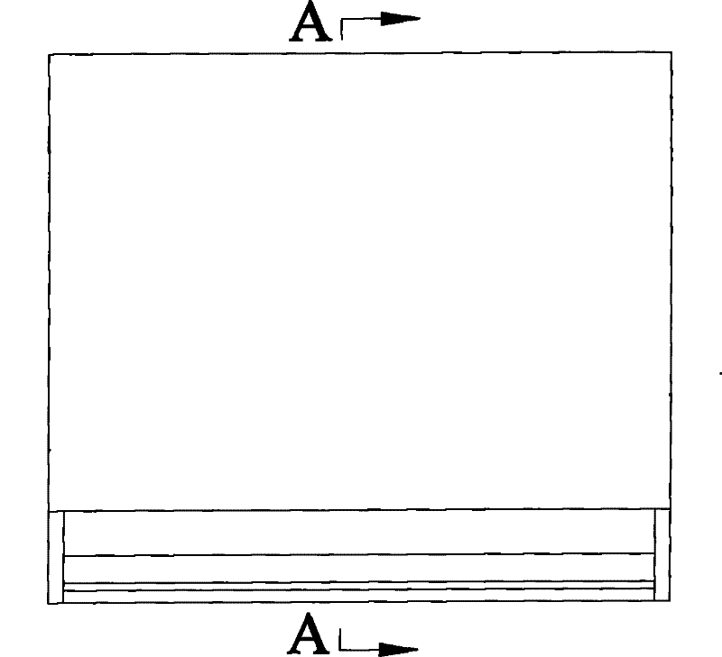
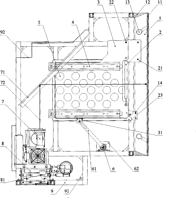
[0022] Such as Figure 1~2 As shown, it is a front view and a transverse cross-sectional view of a schematic diagram of the structure display unit of the present invention, and the transverse cross-sectional view is to clearly show the internal structure of the box and the composition of the optical path. A rear-projection large-screen display unit of a front-maintenance remote control adjustment optical path, which consists of a forward-moving flip screen 1, a left and right support rod 2, a left and right movable support plate 3, a left and right chute 4, a left and right support plate 5, and a synchronous connecting rod 6. It is composed of an imaging device 7, a remote control adjustment device 8, and a building block-type stacked structure box 9.

[0023] Wherein the forward-moving flip-type screen 1 is composed of an imaging screen 11 , a screen frame 12 , a forward-mov...


PUM


Abstract

The invention relates to a front load remote control adjusting light path back projection large screen display unit, which comprises a forward lead tipping screen, a left right knighthead, a left right side movable facing bar, a left right side runner, a left right side shoe plate, a synchronous joint lever, an imaging device, an adjusting device, and a building block system stacking structural case. The left right knighthead, left right side movable facing bar, the left right side runner, the left right side shoe plate, the synchronous joint lever and the imaging device are arranged inside the building block system stacking structure case. The invention improves the rear load building block system stacking structure case display unit exists in present market and at the same time, the invention also improves the front load case display unit which can be matched into two layers existing in present market so that saving backside maintaining space, adjusting and maintaining from the front, and realizing N*M stacking effect with arbitrariness can be realized. Therefore, the invention is a building block system front load remote control adjusting picture display unit which can satisfy all the functions in present markets.

Description

technical field [0001] The invention relates to a rear projection display device, in particular to a rear projection large-screen display unit of a front maintenance type remote control optical path adjustment. Background technique [0002] The rear-projection large-screen display wall is a building block structure composed of N (number of layers)×M (number of cases) display unit boxes. The image it displays is one (multiple) screens divided into N×M by digital technology. After the small picture is transmitted by digital technology, it is assembled into a complete large picture on the display wall. Therefore, each cabinet is required to be light in structure, reliable in load bearing, easy to install, and good in interchangeability. At the same time, it is also required to have reasonable wiring without interference, dust-proof, light-proof and ventilated. At present, the cabinets combined into the display wall adopt the rear debugging structure, that is, a space of not le...

Claims


Application Information

Patent Timeline
Patent Type & Authority Patents(China)
IPC IPC(8): H04N5/74
Inventor 金禾
Owner SHANGHAI LINBELL ELECTRONICS TECH
Features
  • Generate Ideas
  • Intellectual Property
  • Life Sciences
  • Materials
  • Tech Scout
  • Unparalleled Data Quality
  • Higher Quality Content
  • 60% Fewer Hallucinations
Learn More