Transmission-line resonator, high-frequency filter using it, high-frequency module and radio equipment
一种传输线型、谐振器的技术,应用在谐振器、波导型器件、电气元件等方向
- Summary
- Abstract
- Description
- Claims
- Application Information
AI Technical Summary
Problems solved by technology
Method used
Image
Examples
no. 1 Embodiment approach
Next, a transmission line type resonator according to a first embodiment of the present invention will be described with reference to the drawings.
[0013]
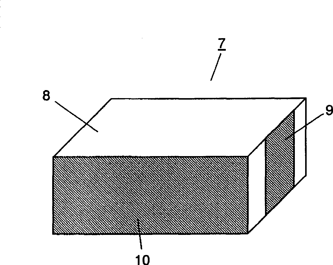
figure 1 It is an outline view showing the transmission line resonator in the first embodiment.
[0014]
exist figure 1 Among them, the transmission line resonator 7 has a laminated body 8 , an external connection terminal 9 and a ground electrode 10 arranged on the end surface of the laminated body 8 .
[0015]
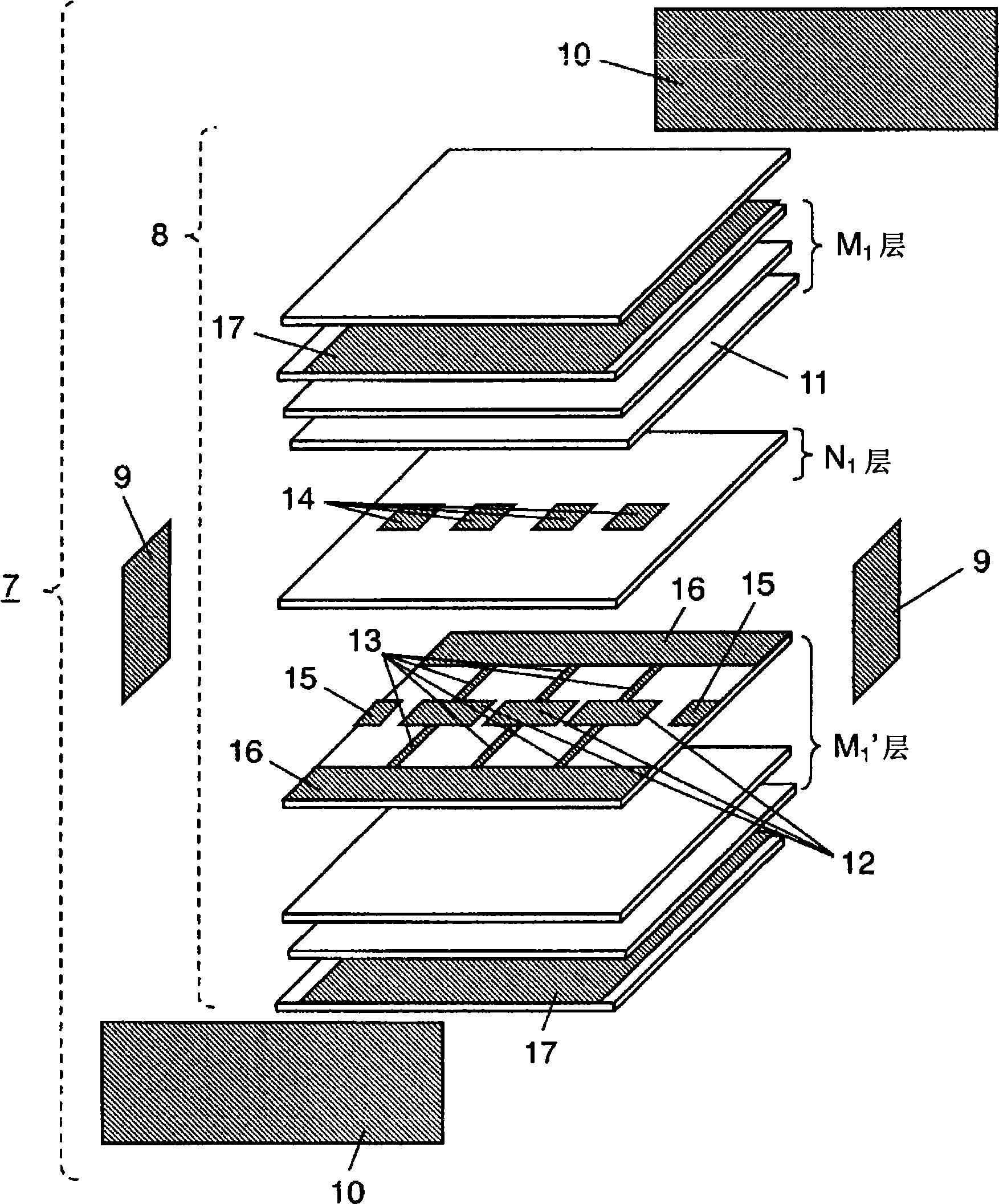
figure 2 It is an exploded perspective view showing the transmission line type resonator of the composite right-hand system and left-hand system in the first embodiment. After stacking multiple layers of dielectric sheets 11 made of ceramics or resins fired simultaneously at low temperature, the transmission line resonator 7 of the composite right-handed system and left-handed system is formed. Further, on a certain dielectric sheet 11, a plurality of line electrodes 12 are arranged linearly with an arb...
no. 2 Embodiment approach
Next, the configuration of the transmission line type resonator of the composite right-hand system and left-hand system in the second embodiment of the present invention will be described. In addition, unless otherwise mentioned, the structure and operation of the transmission line type resonators given the same symbols as those of the first embodiment are the same, and thus will not be described again. Figure 9 Shown is an exploded perspective view of the transmission line resonator of the composite right-hand system and left-hand system in the second embodiment. Figure 10 It is a figure which shows the cross-sectional view in 10-10.
[0035]
In the second embodiment, instead of arranging the capacitive electrode 14 , the line electrode 12 is arranged with positions differently shifted from each other over two layers. In this way, capacitive coupling can be performed between the opposing line electrodes 12 .
[0036]
With this configuration, further miniaturization of ...
no. 3 Embodiment approach
Next, the structure of the transmission line type resonator of the composite right-hand system and left-hand system in the third embodiment of the present invention will be described. In addition, unless otherwise mentioned, the structure and operation of the transmission line type resonators given the same symbols as those of the first embodiment are the same, and thus will not be described again. Figure 11 It is an exploded perspective view of the transmission line type resonator 7 of the composite right-hand system and left-hand system in the third embodiment. Figure 12 It is a figure which shows the sectional view in 12-12.
[0038]
Here, instead of the connection pattern electrode 13 , the line electrode 12 is grounded by the shield pattern electrode 17 via the via hole electrode 18 . via hole electrode 18, as a shunt inductor L L action. In addition, the ground pattern electrode 16 may not be present. In this way, the lateral width of the transmission line resonat...
PUM
 Abstract
Description
Claims
Application Information
 - R&D
- Intellectual Property
- Life Sciences
- Materials
- Tech Scout
- Unparalleled Data Quality
- Higher Quality Content
- 60% Fewer Hallucinations
Browse by: Latest US Patents, China's latest patents, Technical Efficacy Thesaurus, Application Domain, Technology Topic, Popular Technical Reports.
© 2025 PatSnap. All rights reserved.Legal|Privacy policy|Modern Slavery Act Transparency Statement|Sitemap|About US| Contact US: help@patsnap.com


