Pad body improvement structure for ventilation shoe pad

An improved structure and insole technology, applied in the field of elastic insoles, can solve the problems of air flowing into the air chamber, the air in the air chamber is not easy to flow out, and heat sources generated by impact friction

Inactive Publication Date: 2009-08-26
林重仁
View PDF8 Cites 3 Cited by
  • Summary
  • Abstract
  • Description
  • Claims
  • Application Information

AI Technical Summary

Problems solved by technology

[0005] However, the ventilating insole structure that can be seen in the above-mentioned workshops and previous patent cases, because if the upper insole in contact with the sole of the foot is a flat surface, when the foot is lifted off the ground, if the shoe is tight, the air inlet is easily covered by the heel. It makes it difficult for air to flow into the air chamber from the air inlet; when the foot presses down on the insole, if the air outlet is covered by the sole of the foot, the air inside the air chamber is not easy to flow out from the air outlet, and the common disadvantage of unsmooth air circulation
[0006] Moreover, if the air chamber of the above-mentioned ventilating insole structure is composed of upper and lower insoles and a foam pad in the middle, the foam pad with large gaps and low density has a large air capacity, but it is easy to be flattened due to elastic fatigue; On the contrary, the foam pad with small gap and high density has the advantage of good elasticity and is not easy to be crushed, but the air capacity is small, the air is not easy to circulate, and the air passes through the foam pad with high density, and there will be impact friction. The disadvantage of the heat source occurs

Method used


Image

  • Pad body improvement structure for ventilation shoe pad
  • Pad body improvement structure for ventilation shoe pad
  • Pad body improvement structure for ventilation shoe pad

Examples


Embodiment Construction

[0018] The above and other technical features and advantages of the present invention will be described in more detail below in conjunction with the accompanying drawings.

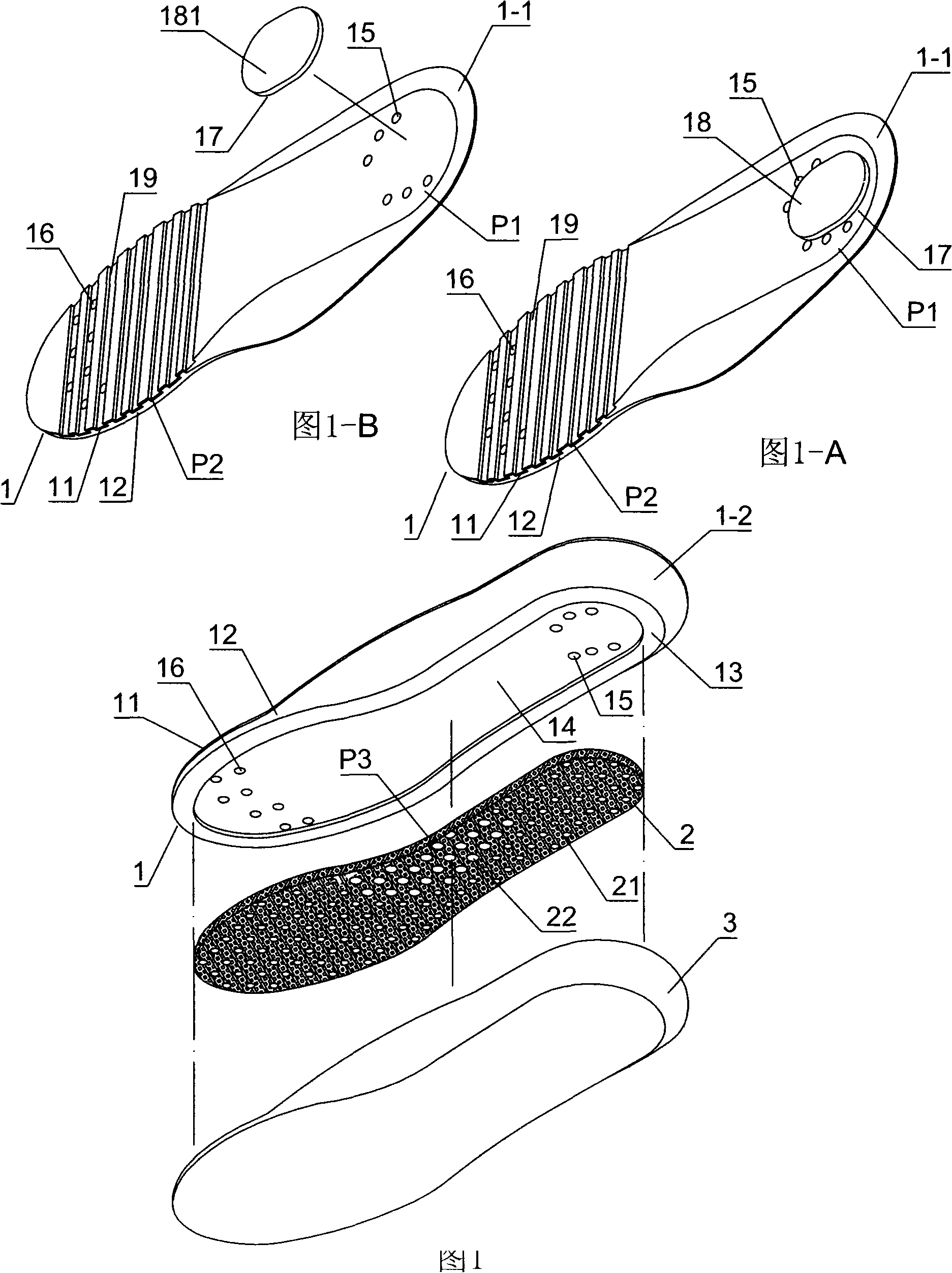
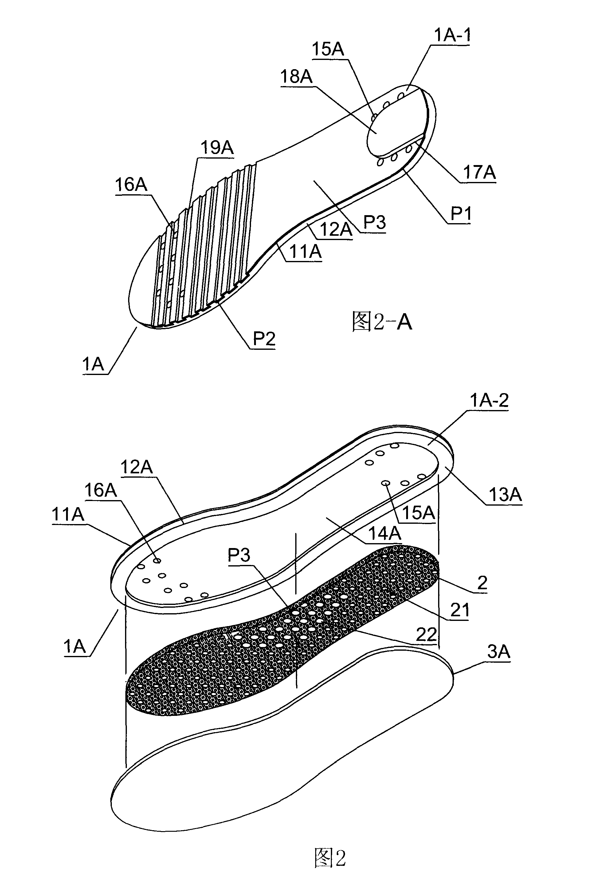
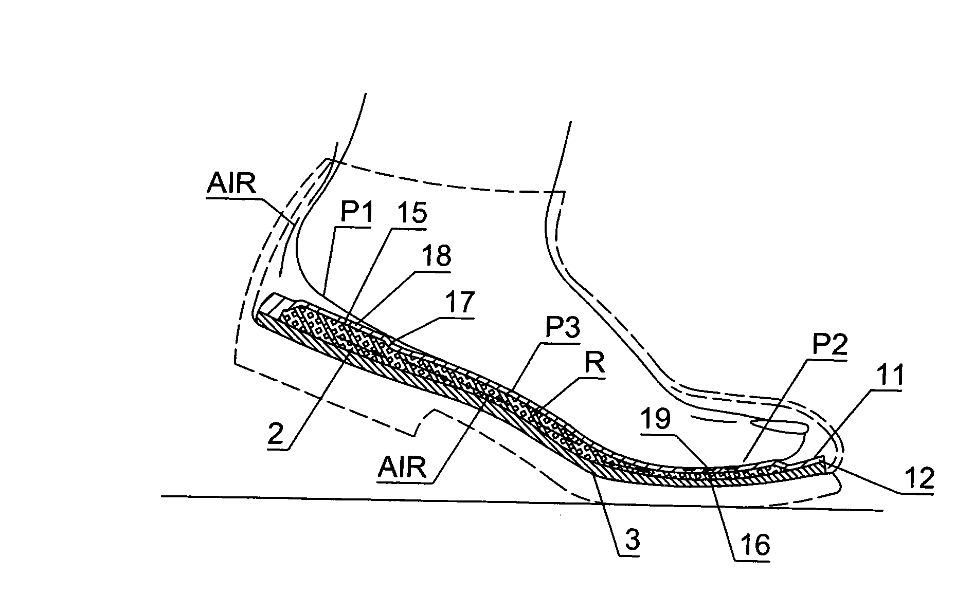
[0019] Please refer to figure 1 , Figure 1-A and figure 2 , Figure 2-A Shown:

[0020] It can be clearly understood that the main purpose of the present invention is that when the plastic material 12, 12A such as cloth or leather 11, 11A can be glued on the surface, when the insole 1, 1A is integrally formed, the heel portion of the front 1-1, 1A-1 must be provided with a protrusion. Face 18,18A; And several air inlets 15,15A are set at edge 17,17A of projection surface 18,18A; And described projection surface 18,18A can be gentle cone (as Figure 1-A shown), or other shapes of cylinders, cones, etc. (such as Figure 2-A shown) are applicable.

[0021] Among them, the setting of the protruding surface 18, 18A can be made when the upper insole 1, 1A is integrally formed; it can also be changed to s...


PUM


Abstract

The invention relates to a pad body improvement structure for a ventilation shoe pad. The pad body improvement structure comprises an upper shoe pad with air inlets and air outlets, a lower shoe pad and a foam pad with smaller middle area; wherein when the upper shoe pad sticking to a plastic material such as cloth or leather is integrally formed, the front face of the upper shoe pad in contact with a sole has a bulging surface at the heel position and a plurality of air inlets arranged at the lower edge of the bulging surface; a plurality of free-form grooves are arranged at a fore sole of the foot in a fit mode, and the bottoms of the grooves are provided with a plurality of air outlets; the foam pad with higher density is used in a fit mode and a plurality of small holes are distributed on the foam pad; and an arch without sustaining pressure is provided with a plurality of big holes through dense punching. The structure can reach optimal ventilation effects of improving the smoothness of the air circulation and increasing the air capacity.

Description

technical field [0001] The present invention relates to an improved pad body structure of a ventilating insole, in particular to an improved elastic pad composed of an upper insole with an air inlet and an outlet, a lower insole and a foam pad with a smaller interlayer area. Insole; when the upper insole is formed, the contact surface with the sole of the foot is provided with several protruding surfaces with air inlets at the lower edge of the heel; and several arbitrary shapes are arranged on the forefoot, and several grooves are arranged at the bottom of the groove. There are grooves distributed in each air outlet, and a foam pad with high density and compression resistance is used, and several small holes are punched on the foam pad; while in the arch of the foot that is not under pressure, densely punched A number of large holes are provided; the effect of the structure to achieve air circulation and ventilation can be significantly enhanced. Background technique [00...

Claims


Application Information

Patent Timeline
Patent Type & Authority Applications(China)
IPC IPC(8): A43B17/08
CPCA43B13/12A43B7/144A43B17/08A43B17/14
Inventor 林重仁
Owner 林重仁
Why Eureka
Try Eureka