Magazine device

A storage box and conveying device technology, used in packaging, transportation and packaging, thin material handling, etc., can solve problems such as failures, limit the maximum capacity of reserve storage boxes, etc., and achieve the effect of improving loading and conveying

Inactive Publication Date: 2009-08-26
KHS GMBH
View PDF0 Cites 5 Cited by
  • Summary
  • Abstract
  • Description
  • Claims
  • Application Information

AI Technical Summary

Problems solved by technology

In the case of large storage magazines, this pressing force can be increased to such an extent that the removal device, which usually takes place by means of a vacuum suction device, can no longer reliably grip the blank, which can lead to malfunctions
In particular, this also undesirably limits the maximum capacity of the storage magazine

Method used


Image

  • Magazine device
  • Magazine device

Examples


Embodiment Construction

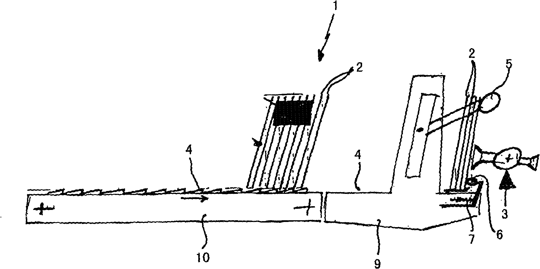
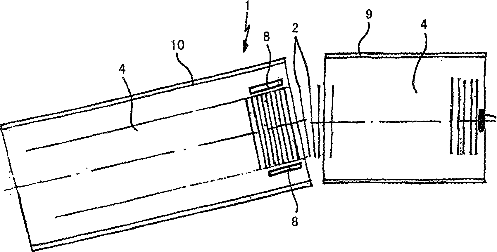
[0018] exist figure 1 and figure 2 The magazine arrangement indicated generally at 1 is shown in detail in . The magazine arrangement serves to store and transport a series of flat elements made of cardboard, for example blanks 2 . A removal device, indicated generally at 3 , in the form of a vacuum gripper removes the blanks 2 at the end of the device 1 in order to feed these blanks to the packaging machine. The blanks 2 are placed upright on the conveyor chain 4 in the region of the magazine part 10 of the device 1 and moved along the conveying direction of the chain 4 until they abut against the blanks 2 already present. The inclination of the individual links of the conveyor chain 4 in the conveying direction makes it possible to easily move in this direction and at the same time prevent the lower parts of the elements from slipping away.

[0019] In the region of the vacuum gripper 3 there is provided a stop 5 against which the blank 2 rests with its upper edge. At t...


PUM


Abstract

The invention relates to a magazine device (1) for adjacent, planar elements (2), comprising at least one conveying apparatus (4) and at least one removing mechanism (3). The aim of the invention is to improve said magazine device (1) so as to increase the maximum capacity thereof and render the same more user-friendly and less prone to malfunction. Said aim is achieved by providing a retaining mechanism (8) in front of the removing mechanism (3) in the direction of travel.

Description

technical field [0001] The invention relates to a magazine arrangement according to the preamble of claim 1 and to a method for controlling such a magazine arrangement. Background technique [0002] Such a magazine device is used, for example, to store and transport flat elements, such as cardboard blanks and the like, so that they can be fed, for example, to a packaging machine. In order to allow a uniform supply and to ensure a continuous infeed at the often high withdrawal speeds, such magazines must have a large capacity and be easily filled with new blanks. [0003] The conventional way to do this is to use a conveyor section, in which blanks arranged vertically and next to each other are placed on a conveyor chain. The conveyor chain transports the blanks in the direction of the removal device. In order to prevent these vertically arranged elements from tipping over, a slideable square is arranged on the end side of the conveyor device, which must be retractable for ...

Claims


Application Information

Patent Timeline
Patent Type & Authority Applications(China)
IPC IPC(8): B65B43/18B65H1/24B65H1/02
CPCB65B43/185B65H1/24B65H1/02B65H2701/1764
Inventor H·范黑克T·勒里耶D·奥尔特曼M·约里森J·迪佩尔
Owner KHS GMBH
Why Eureka
Try Eureka