
Hydraulic locking device of ankle joint of artificial foot with adjustable heel height

A locking device and height-adjustable technology, applied to artificial legs, etc., can solve the problems of non-replaceable feet, inconvenience for users, and inability to steplessly adjust the heel height, so as to reduce the strength requirements, change the height of artificial heels, and reduce costs. Effect

Inactive Publication Date: 2009-09-02
UNIV OF SHANGHAI FOR SCI & TECH
View PDF0 Cites 20 Cited by
  • Summary
  • Abstract
  • Description
  • Claims
  • Application Information

AI Technical Summary

Problems solved by technology

But at least one of the following problems exists in every existing related product on the market: 1) different foot plates with other functions cannot be replaced, and only a matching foot plate of the company can be used, and its heel height can be adjusted to the maximum The distance can only reach 5cm; 2) It is necessary to change the rotation angle of the ankle joint by allowing the connecting parts of the ankle joint to slide in an arc-shaped slideway. This method usually requires the help of other people to complete the adjustment, so that it is difficult to achieve the best Alignment effect and inconvenience to users; 3) Heel height cannot be adjusted steplessly within a certain range

Method used


Image

  • Hydraulic locking device of ankle joint of artificial foot with adjustable heel height
  • Hydraulic locking device of ankle joint of artificial foot with adjustable heel height
  • Hydraulic locking device of ankle joint of artificial foot with adjustable heel height

Examples


Embodiment Construction

[0020] The present invention will be further described below in conjunction with the accompanying drawings and embodiments.

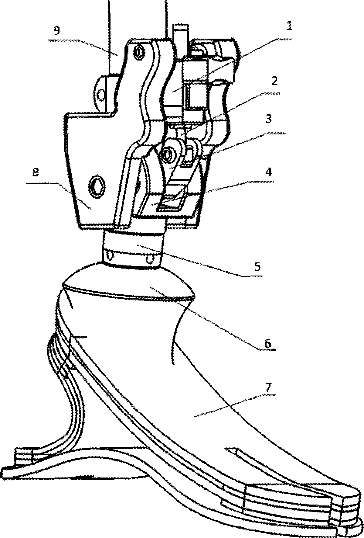
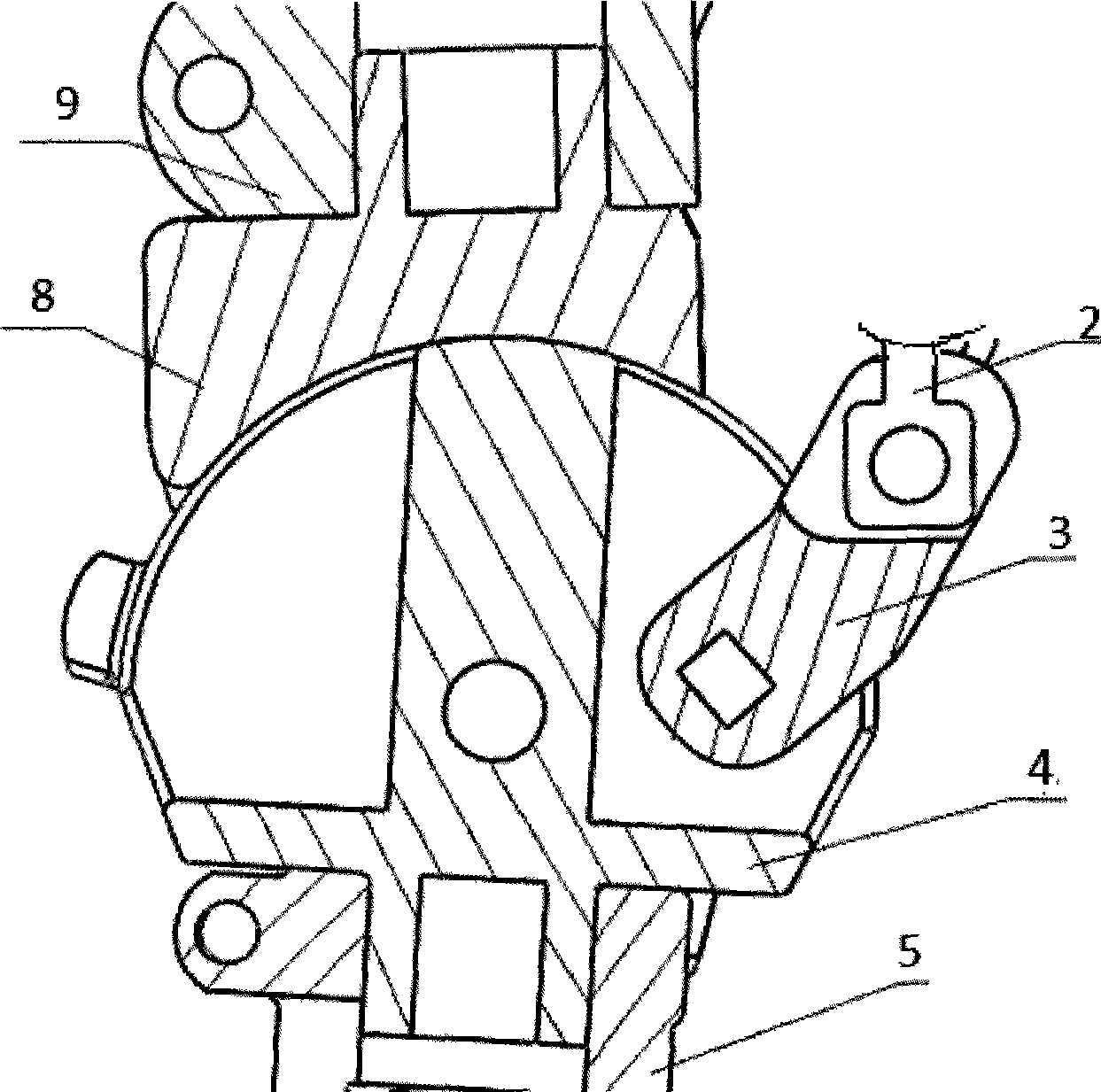
[0021] as attached figure 1 As shown, the hydraulic locking device of the height-adjustable artificial ankle joint of the present invention includes: a miniature hydraulic cylinder 1, a piston rod 2, an ankle joint connecting rod 3, a rotating ankle joint 4, a standard two-way joint 5, and a standard ankle joint joint 6 , Ordinary prosthetic foot 7, artificial ankle sleeve 8, standard calf tube 9.

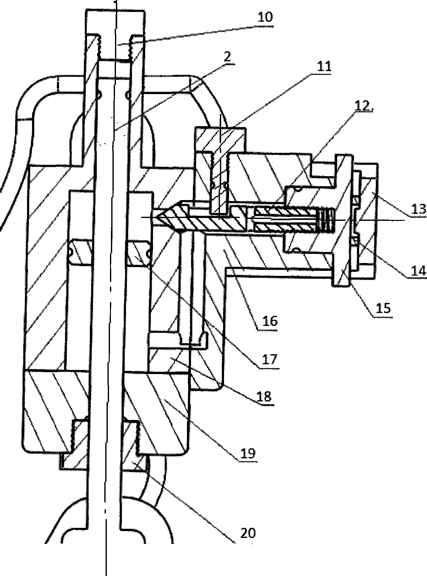
[0022] The upper and lower main chambers on both sides of the piston 17 communicate with each other through an oil fluid communication mechanism. The installation channel plate 16 of the oil communication mechanism is installed with a locking and unlocking mechanism.

[0023] The oil-liquid communication mechanism includes the main hydraulic cylinder block 18, and the access plate 16 is installed. There is a plane on the right side of the main hydraulic cy...


PUM


Abstract

The invention relates to a hydraulic locking device of an ankle joint of an artificial foot with an adjustable heel height. The hydraulic locking device comprises a main hydraulic cylinder, a piston rod, a piston and an ankle joint connecting rod connected with the piston rod. An upper main cavity and a lower main cavity of two sides of the piston in the main hydraulic cylinder are communicated through a hydraulic oil communication mechanism; and the inside of the hydraulic oil communication mechanism is provided with a locking and unlocking mechanism. The hydraulic locking device utilizes the incompressibility of hydraulic oil so that the position of the piston in a hydraulic cylinder is changed up and down along the flow of the hydraulic oil in a hydraulic oil passage, further drives the ankle joint to rotate so as to change the angle of a base plate of the artificial foot relative to the level, thereby achieving the aim of changing the heel height of the artificial foot. In addition, as the hydraulic locking device can carry out stepless regulation on the flow rate of the hydraulic oil, the hydraulic locking device can carry out stepless regulation on the heel height of the artificial foot till the piston achieves the largest journey. Moreover, a locking pin valve, an adjusting knob and a pin valve fixing sleeve are added into the hydraulic oil passage; and the hydraulic locking device can conveniently adjust and lock the heel height through the rotation of the adjusting knob and can realize the replacement and use of the base plate of the artificial foot.

Description

technical field [0001] The invention relates to a bionic artificial ankle joint device based on hydraulic locking and adjustment, in particular to a miniature hydraulic cylinder for adjusting the height of the artificial heel and a bionic artificial foot ankle joint mechanism. Background technique [0002] For lower limb prostheses, the quality and performance are important, but it is also very important for the wearer to install the prosthesis correctly. One of the very important indicators is correct alignment. Lower limb prostheses must be adjusted on the line in order to achieve the purpose of being suitable for amputees. Improper alignment will seriously affect the patient's balance and stability during standing and walking. The static alignment of the lower limb prosthesis is to determine the relative position and angle of the socket, each lower limb joint, prosthetic foot and the height of the prosthesis in three-dimensional space. And the height of the heel of the ...

Claims


Application Information

Patent Timeline
IPC IPC(8): A61F2/66
Inventor 喻洪流简卓胡加华赵展
Owner UNIV OF SHANGHAI FOR SCI & TECH
Learn More