
Method and device for drying printed corrugated board

A technology of corrugated cardboard and drying equipment, applied in printing, printing machines, post-processing of printing, etc., to achieve the effects of reducing production costs, improving light source utilization, and reducing energy consumption

Active Publication Date: 2009-09-02
刘为成
View PDF0 Cites 4 Cited by
  • Summary
  • Abstract
  • Description
  • Claims
  • Application Information

AI Technical Summary

Problems solved by technology

The printing and drying methods and devices in the prior art do not fully consider the influence of the above factors, and there are problems in drying effect, effective use of energy, fire control, etc., and further improvement is needed

Method used


Image

  • Method and device for drying printed corrugated board
  • Method and device for drying printed corrugated board
  • Method and device for drying printed corrugated board

Examples


Embodiment 1

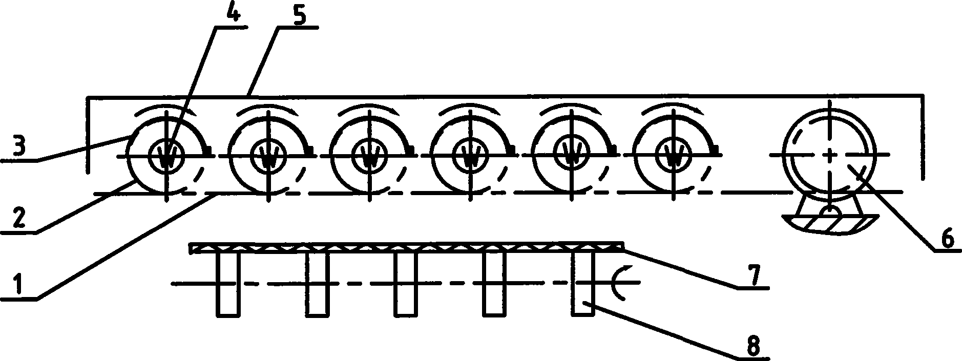
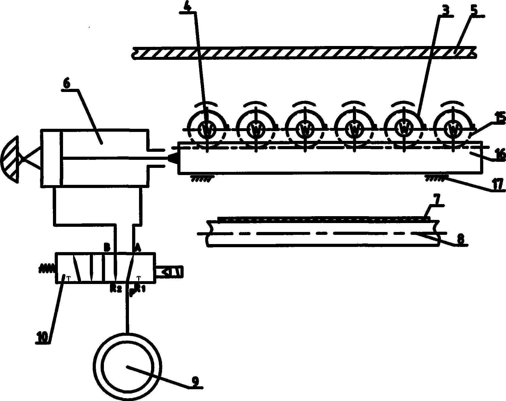
[0028] A printing and drying method for corrugated cardboard, which uses infrared rays to directly irradiate the corrugated cardboard to make it dry. The infrared rays are emitted by the infrared lamp tube, and the length direction of the infrared lamp tube is set to be parallel to the traveling direction of the corrugated cardboard. Six infrared lamps are arranged in parallel in one group, and the number of groups is two groups, and each infrared lamp and each group of infrared lamps are independently controlled. Each infrared lamp tube is provided with a reflective shield that can reflect the emitted rays to the corrugated cardboard or block the emitted rays from the corrugated cardboard. The reflective protective cover is an active mode, and the activity of the reflective protective cover is an automatic control mode.

[0029] A corrugated cardboard printing and drying device implementing the above method, such as figure 1 and figure 2 As shown, it is set on the plane c...

Embodiment 2

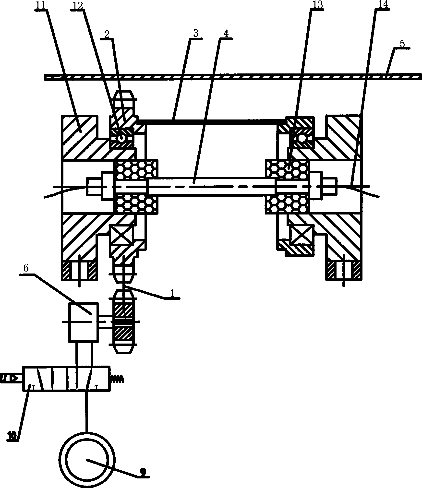
[0036] The invention relates to a printing and drying method of corrugated cardboard, which uses infrared rays to directly irradiate the corrugated cardboard to make it dry. The infrared rays are emitted by the infrared lamp tube, and the length direction of the infrared lamp tube is set to be parallel to the traveling direction of the corrugated cardboard. Six infrared lamps are arranged in parallel in one group, and the number of groups is two groups, and each infrared lamp is independently controlled. Each infrared lamp tube is provided with a reflective shield that can reflect the emitted rays to the corrugated cardboard or block the emitted rays from the corrugated cardboard. The reflective protective cover is an active mode, and the activity of the reflective protective cover is an automatic control mode.

[0037] A corrugated cardboard printing and drying device implementing the above method, such as figure 1 , Figure 4 As shown, it is set on the flat corrugated car...


PUM


Abstract

The invention relates to a method and a device for drying a printing ink layer of a corrugated board. The method is to directly irradiate the corrugated board with infrared rays, and the lengthwise direction of light tubes emitting the infrared rays is parallel to the direction in which the corrugated board advances. A plurality of infrared light tubes are arranged parallelly in group, each and each group of the infrared light tubes can be controlled independently. The device is arranged on a corrugated board conveying device, and the lengthwise direction of the infrared light tubes is consistent with the direction in which the corrugated board conveying device advances. Each infrared light tube is provided with a reflecting protective cover for reflecting the light emitted by the infrared light tube onto the corrugated board or protecting the corrugated board from the light emitted by the infrared light tube. The protective cover is arranged in a mode of automatically-controlled motion. The invention prolongs the time of the irradiation of corrugated board by light emitted by each light tube and improves efficiency. Light tubes in areas not to be dried can be turned off to save energy. In case of sudden vehicle stop, the rays are prevented from irradiating the corrugated board so as to avoid fire.

Description

technical field [0001] The invention relates to a printing drying method and a printing drying device for paper materials, belonging to the field of printing technology and equipment, in particular to a printing ink layer drying method and drying device for corrugated cardboard. Background technique [0002] In the current color printing technology of paper materials such as corrugated cardboard, the ink layer on the surface of the corrugated cardboard is required to dry as soon as possible, that is, the "wet-on-dry" printing mode is adopted. After the last color is printed, a dry ink layer can be formed. Conducive to stacking or winding. The use of infrared drying device to speed up the drying of the ink layer is a common method in this industry. The principle is that the infrared rays are directly irradiated on the ink layer of the corrugated cardboard, and the ink layer of the corrugated cardboard absorbs infrared rays and directly converts it into thermal vibration. The...

Claims


Application Information

Patent Timeline
Patent Type & Authority Applications(China)
IPC IPC(8): B41M7/00B41F23/04B41F33/00
Inventor 刘为成
Owner 刘为成
Learn More