Liquid surface sealing of clip-shaped slot structure

A liquid surface and sealing device technology, which is applied in the connection of packing seal with fluid pressure, pipes/pipe joints/fittings, passing components, etc., can solve the problem of liquid surface sealing of the return palace groove structure that has not yet been seen, and achieve resistance Small size, good sealing, safe and reliable operation

Inactive Publication Date: 2009-09-02
方建升 +1
View PDF0 Cites 1 Cited by
  • Summary
  • Abstract
  • Description
  • Claims
  • Application Information

AI Technical Summary

Problems solved by technology

So far, there is no device that utilizes the liquid surface seal of the return palace groove structure

Method used


Image

  • Liquid surface sealing of clip-shaped slot structure
  • Liquid surface sealing of clip-shaped slot structure

Examples


Embodiment Construction

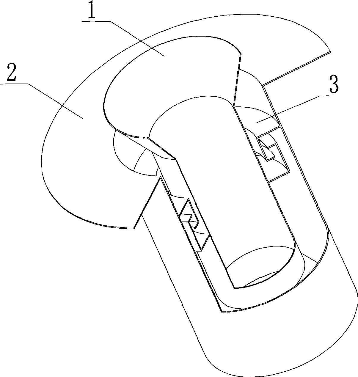
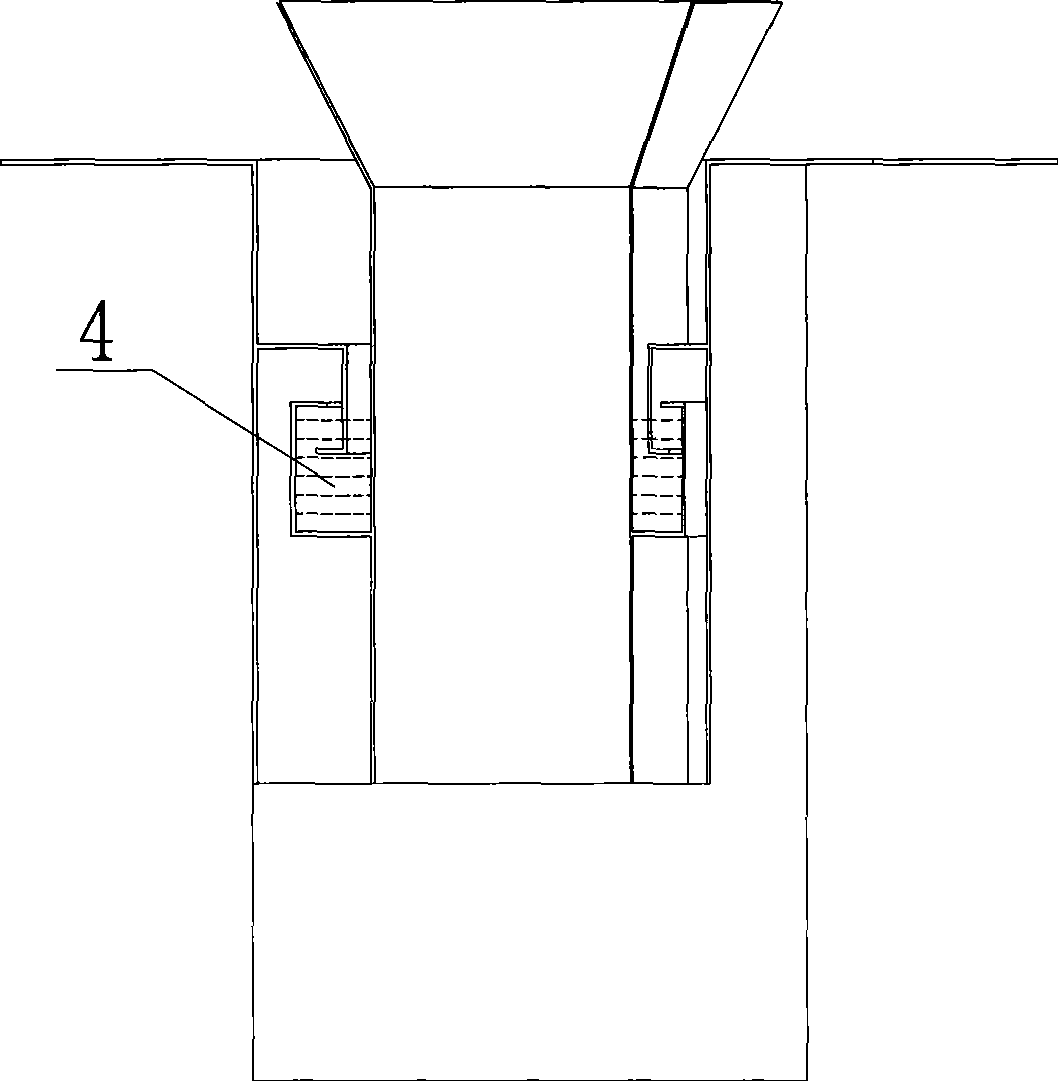
[0012] As shown in the figure, the liquid surface sealing device of the return palace groove structure, the working principle of the liquid surface sealing structure device is as follows: the 1-fixed element is inverted between the nozzle of the funnel and the nozzle of the 2-rotating element, and 3- The structure of the return palace groove is in the form of gap connection, and a certain amount of 4-working fluid is added to the structure of the 3-return palace groove, and the height of the liquid level must meet the design requirements. When the air flows through the 1-fixed element inverted funnel nozzle into the 2-rotating element tube, due to the sudden expansion of the cross-sectional area of ​​the nozzle, the flow rate increases, and its pressure drops to form a violent vortex, the speed is almost completely lost, and the pressure gradually decreases, starting from 4-working The space between the liquid level and the cavity of the 3-return palace groove structure is alwa...


PUM


Abstract

The invention relates to a liquid surface sealing device of a clip-shaped slot structure and belongs to the field of environmental protection. Gap connection in the form of the clip-shaped slot structure is adopted between an inverted funnel pipe opening of a fixed element and a pipe opening of a rotating element, and a certain amount of working solutions are added into the clip-shaped slot structure, thus achieving the goal of flexible connection between mobile and static elements as well as the sealing without mechanical friction.

Description

technical field [0001] The invention relates to a liquid surface sealing device with a return palace groove structure, belonging to the field of environmental protection. Background technique [0002] There are two commonly used sealing devices, generally with stuffing box (asbestos rope soaked in oil or coated with graphite) and mechanical (end face) seal. Up to now, there is no device that utilizes the liquid surface seal of the return palace groove structure. Contents of the invention [0003] The object of the invention is to provide a liquid surface sealing device with a return palace type tank structure. [0004] The technical solution adopted in the present invention is: the fixed element is inverted between the nozzle of the funnel and the nozzle of the rotating element, and the gap connection is adopted in the form of a return palace groove structure, and a certain amount of working fluid is added in the return palace groove structure. The height must meet the d...

Claims


Application Information

Patent Timeline
Patent Type & Authority Applications(China)
IPC IPC(8): F16L17/02
Inventor 方建升王江
Owner 方建升
Why Eureka
Try Eureka