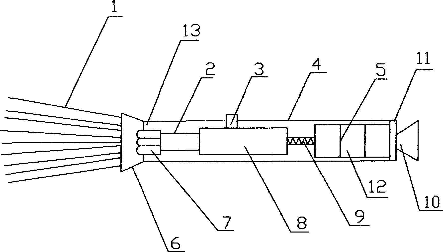
LED optical small flashlight

An optical fiber and torch technology, applied in the field of lighting equipment, can solve the problems of low luminous efficiency, soft light, slow transmission, etc., and achieve the effect of soft and pure color, soft light color and high price

Inactive Publication Date: 2009-09-02
WUXI LED TRUST PHOTONIC TECH
View PDF0 Cites 1 Cited by
  • Summary
  • Abstract
  • Description
  • Claims
  • Application Information

AI Technical Summary

Problems solved by technology

[0003] The purpose of the present invention is to overcome the defects of low luminous efficiency, low energy saving, soft light and slow transmission of the original traditional small flashlight, thereby providing a

Method used


Image

  • LED optical small flashlight

Examples


Example Embodiment

[0011] The present invention will be further described below in conjunction with the drawings:

[0012] The LED optical fiber small flashlight of the present invention includes a lamp body part 13 and a driving part 12.

[0013] The lamp body part 13 includes an optical fiber 1, a lamp tube 4, a front cover 6, a rope hook 10, and a rear cover 11. The optical fiber 1 is located at the head of the small LED optical torch and is used to transmit the visible light emitted by the LED 7. The optical fiber 1 is the abbreviation of optical fiber, which is made of glass or plastic fiber, and uses the principle of total reflection of light to transmit the light. The lamp tube 4 is located between the front cover 6 and the rear cover 11, and is used to place the various components in the driving part 12. The front cover 6 is located at one end of the optical fiber 1, and is used to fix the optical fiber 1 on the front cover 5. The hook 10 is located at the tail of the back cover 11 and can b...


PUM


Abstract

The invention relates to lighting equipment, in particular to an LED optical small flashlight adopting an LED as a light source. An optical fiber 1 is made of fiber glass or plastic fibers, and transmits light by adopting a light total reflection principle to make the light more soft and bright so as to greatly reduce light decay.

Description

technical field [0001] The invention relates to a lighting device, in particular to a small LED optical fiber torch using a light emitting diode as a light source. Background technique [0002] The small flashlights on the market now include small ball lamp flashlights and small LED flashlights, but they all have their own shortcomings. The LED optical fiber small flashlight of the present invention uses plastic optical fibers as the transmission material, and its lighting system has soft light color and no light pollution. Optical fiber decorative lighting uses the method of filtering the spectrum to change the color of the light source. After being transmitted through the optical fiber, the color is softer and purer, giving people a very prominent visual effect. Contents of the invention [0003] The purpose of the present invention is to overcome the defects of low luminous efficiency, low energy saving, soft light and slow transmission of the original traditional small...

Claims


Application Information

Patent Timeline
IPC IPC(8): F21L4/00F21V8/00F21V21/08F21V23/00F21Y101/02F21Y115/10
Inventor 缪刚正周炜陈雷中
Owner WUXI LED TRUST PHOTONIC TECH
Why Eureka
Try Eureka