Method for detecting conducted susceptibility

A detection method and sensitivity technology, applied in the direction of measuring electricity, measuring devices, measuring electrical variables, etc., can solve the problems of high cost, time-consuming and labor-intensive

Active Publication Date: 2009-09-02
BEIHANG UNIV
View PDF0 Cites 12 Cited by
  • Summary
  • Abstract
  • Description
  • Claims
  • Application Information

AI Technical Summary

Problems solved by technology

[0005] The traditional limit value level is obtained through a large number of simulations and

Method used


Image

  • Method for detecting conducted susceptibility
  • Method for detecting conducted susceptibility
  • Method for detecting conducted susceptibility

Examples


Embodiment Construction

[0053] The present invention will be further described in detail with reference to the accompanying drawings and embodiments.

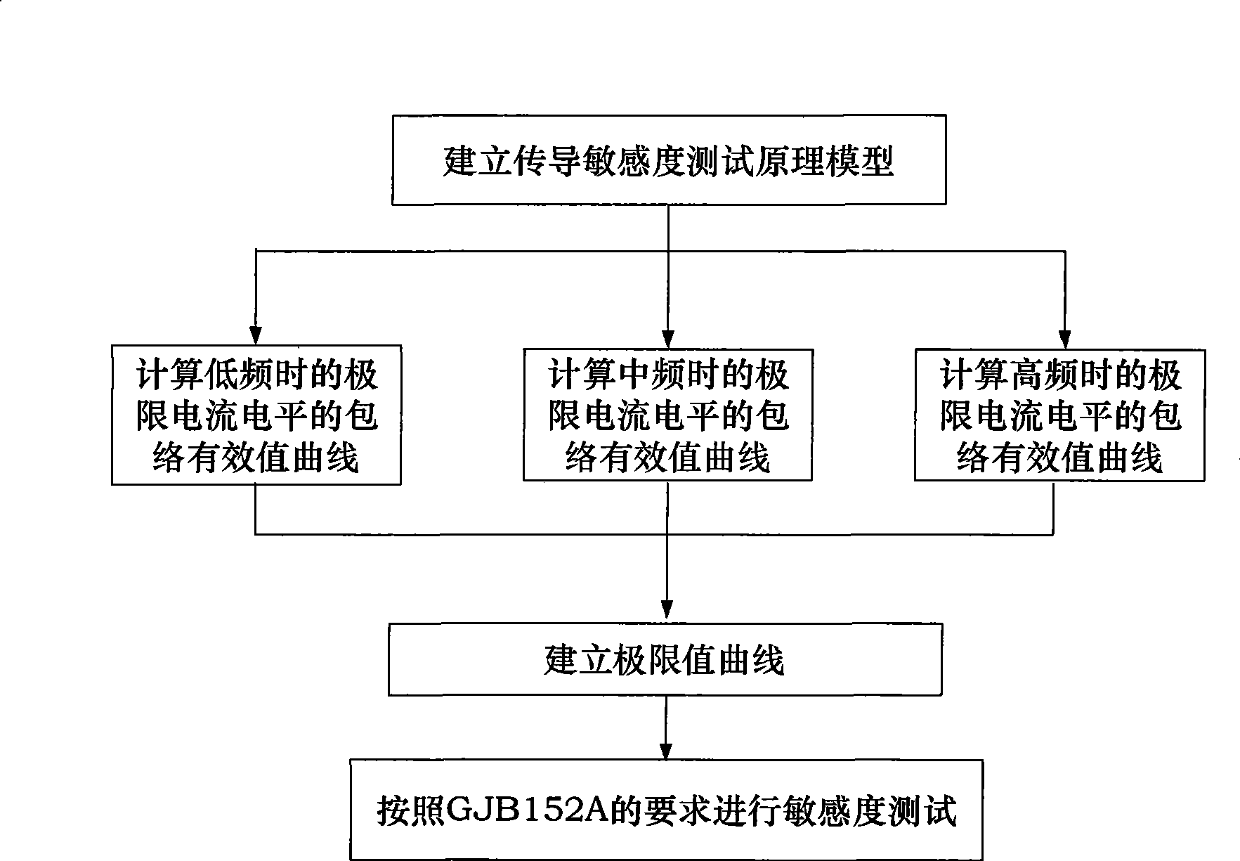
[0054] A kind of conduction sensitivity detection method of the present invention, such as figure 1 The shown is achieved through the following steps:

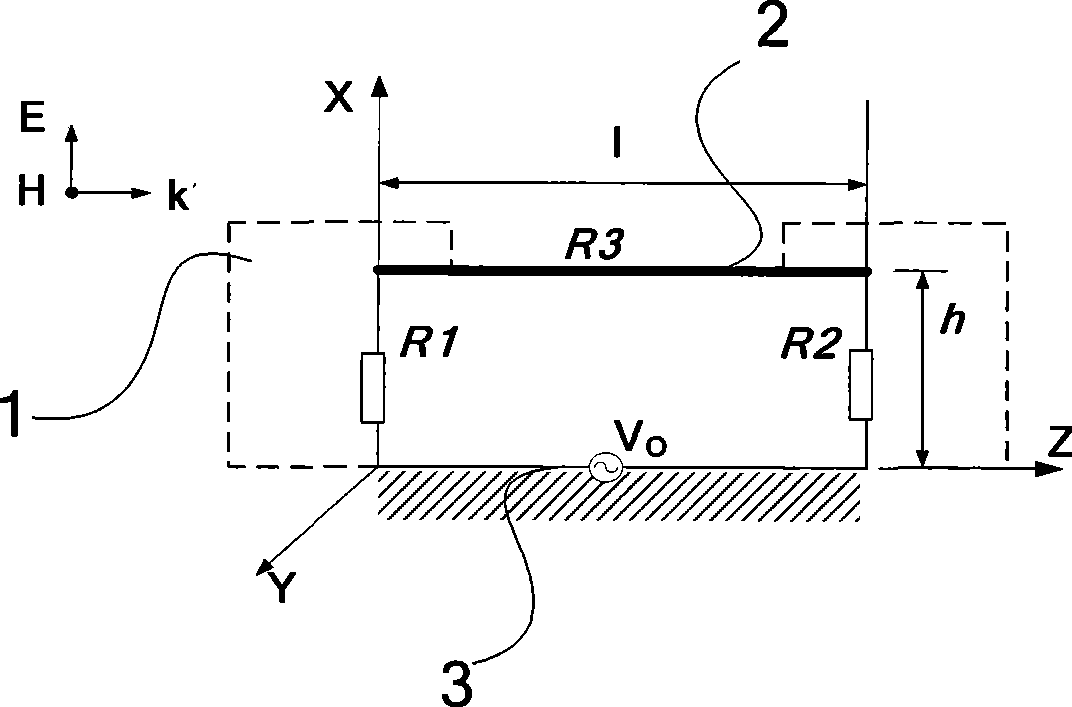
[0055] Step 1: Establish the principle model of conduction sensitivity test.

[0056] like figure 2 As shown, it represents the installation situation of most cables: the tested cable 2 with a length l is installed above the metal interface 1 of the test equipment, and the height from the metal reflective surface 3 (ie "ground") is h (l>>h) . The tested cable 2 forms a loop through the connected equipment and the metal reflective surface 3 . The impedance of the loop is composed of the load resistances R1 and R2 between the two ends of the cable 2 and the ground, and the loss R3 of the cable 2.

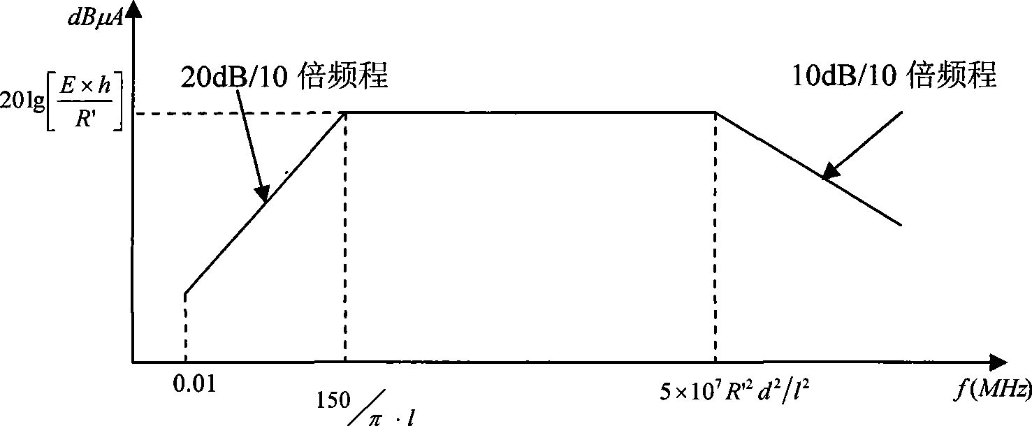
[0057] Step 2: Establish limit value curve;

[0058] The interference signal generated by the signa...


PUM


Abstract

The invention discloses a method for detecting conducted susceptibility, which comprises the following steps: firstly, a conducted susceptibility testing principle model is established; secondly, an ultimate value curve is established; and thirdly, a sensitivity test is carried out by applying the ultimate value curve established in the second step. The invention can completely and accurately check a system level conducted sensitivity testing result, and can obtain the ultimate value curve and a sensitivity ultimate value electrical level, therefore, a system level conducted sensitivity test has an accurate testing basis and a testing standard, and the system level test check is more complete and accurate.

Description

technical field [0001] The invention relates to the field of electromagnetic compatibility testing, in particular to a conduction sensitivity detection method. Background technique [0002] Any electrical, electronic equipment and subsystems will inevitably feed back electromagnetic energy to the power line when they are working, and at the same time leak and radiate electromagnetic energy from the casing, interconnection lines, antenna feeders, etc. to the space. These intentional and unintentional electromagnetic energies constitute the electromagnetic environment at a certain time and place, and the complex and harsh electromagnetic environment is a potential source of interference for the site equipment. Equipment-level electromagnetic emission and sensitivity measurement is a means to evaluate the EMC level of equipment, and it is also the basis for taking EMI measures. EMC testing can be summarized into 4 categories: radiated emission test, radiated sensitivity test, ...

Claims


Application Information

Patent Timeline
IPC IPC(8): G01R31/00
Inventor 戴飞苏东林李益民谢树果
Owner BEIHANG UNIV
Why Eureka
Try Eureka