
Grounding method of primary coil N end of relatively semi-insulating electromagnetic voltage transformer and iron core

A technology of voltage transformer and grounding method, which is applied in the direction of transformer/inductor coil/winding/connection, inductor, transformer/inductor core, etc., which can solve the problems of burning transformer and affecting product insulation performance, etc.

Inactive Publication Date: 2009-09-02
厦门大一互科技有限公司
View PDF0 Cites 1 Cited by
  • Summary
  • Abstract
  • Description
  • Claims
  • Application Information

AI Technical Summary

Problems solved by technology

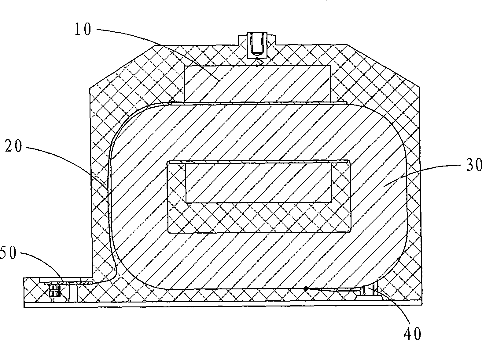
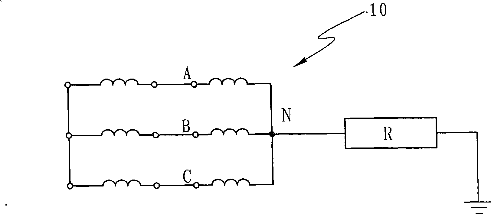
While the iron core 30 is connected to the installation base plate insert 40, no matter whether the product is running or not, the iron core 30 is always guaranteed to be effectively grounded. In this state, when the N terminal 20 of the primary coil 10 of the product adopts an ineffective grounding method, that is, as figure 2 As shown, the N-terminal 20 of the primary coil 10 is grounded through a large resistance R, and is not directly grounded. If resonance or other faults occur (such as the line is single-to-ground), the N-terminal 20 and the iron core 30 will generate a potential difference that reaches the maximum phase voltage. , when the potential difference is greater than 3KV or 5KV, it will affect the insulation performance of the product, and in severe cases, the transformer can be burned

Method used


Image

  • Grounding method of primary coil N end of relatively semi-insulating electromagnetic voltage transformer and iron core
  • Grounding method of primary coil N end of relatively semi-insulating electromagnetic voltage transformer and iron core
  • Grounding method of primary coil N end of relatively semi-insulating electromagnetic voltage transformer and iron core

Examples


Embodiment Construction

[0015] Such as image 3 Shown is a preferred embodiment of the present invention.

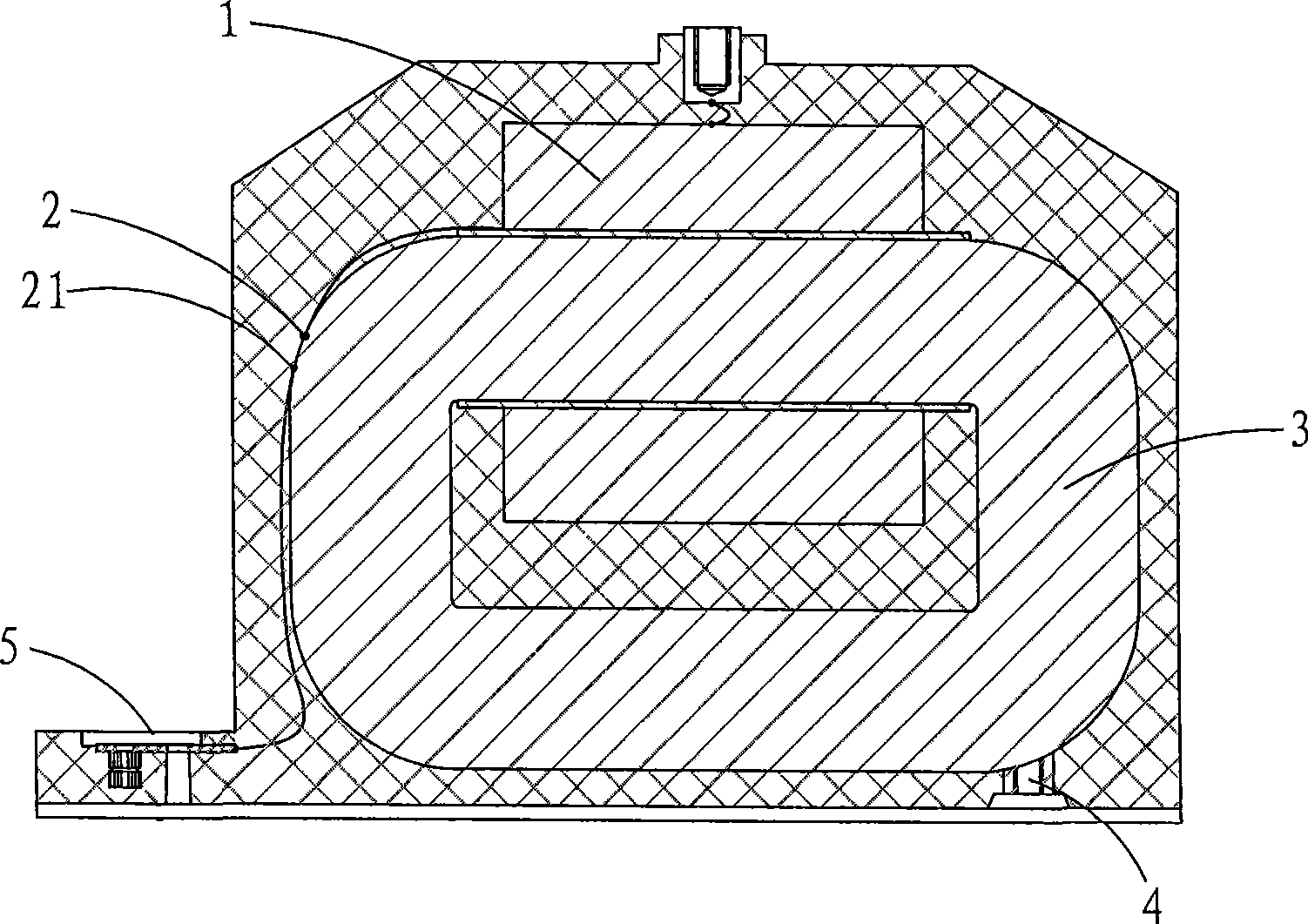
[0016] The invention discloses a method for grounding the N terminal of the primary coil of a relatively semi-insulated electromagnetic voltage transformer and the iron core. To lead out the N-terminal 21, specifically, the connection point between the N-terminal 2 of the primary coil 1 and the core 3 and the point where the N-terminal 21 is drawn out from the core 3 coincide, or as image 3 As shown, the connection point between the N-terminal 2 of the primary coil 1 and the core 3 is separated from the point where the N-terminal 21 is drawn from the core 3, and then the N-terminal 21 and the connecting piece 5 are grounded, and the N-terminal 21 It can be effectively grounded or grounded through a large resistance (such as figure 2 shown). The core 3 is still connected to the mounting base insert 4 .

[0017] Compared with the prior art, the present invention directly connects the N term...


PUM


Abstract

The invention discloses a grounding method of a primary coil N end of a relatively semi-insulating electromagnetic voltage transformer and an iron core. An outgoing line of the primary coil N end is connected with the iron core inside a casting body, and the N end is then led out of the iron core and subjected to operational grounding with a connecting sheet. In the method, when the product does not operate, neither of the N end and the iron core is grounded; and when the product operates, the N end and the iron core are grounded simultaneously, and the iron core is connected with an insert of an installation base plate. When malfunction occurs, the electric potential of the iron core and the N end which are connected together is the same, electric potential difference does not exist at the grounding point inside the casting body, the product can not be damaged, and the insulation safety performance and normal use of the transformer are ensured.

Description

technical field [0001] The invention relates to the technical field of electromagnetic voltage transformers, and relates to the grounding method of the N terminal of the primary coil of the relatively semi-insulated electromagnetic voltage transformer and the iron core. Background technique [0002] In the prior art, relatively ground semi-insulated electromagnetic voltage transformers such as figure 1 As shown, the N-terminal 20 of the primary coil 10 is connected to the connecting piece 50 by a separate outlet, and is not connected to the core 30 inside. This makes the N-terminal 20 have an insulation level of 3KV or 5KV to the ground and the secondary coil under non-operating conditions. While the iron core 30 is connected to the installation base plate insert 40, no matter whether the product is running or not, the iron core 30 is always guaranteed to be effectively grounded. In this state, when the N terminal 20 of the primary coil 10 of the product adopts an ineffecti...

Claims


Application Information

Patent Timeline
IPC IPC(8): H01F38/24H01F27/29H01F27/24H01F41/00
Inventor 王继元李静惠兆鹏符祥强
Owner 厦门大一互科技有限公司
Learn More