
Semiconductor device and manufacturing method of the same

A manufacturing method and semiconductor technology, applied in the direction of semiconductor/solid-state device manufacturing, semiconductor devices, semiconductor/solid-state device components, etc., can solve problems such as easy cracking, and achieve the effect of suppressing damage

Inactive Publication Date: 2009-09-02
MITSUBISHI ELECTRIC CORP
View PDF7 Cites 13 Cited by
  • Summary
  • Abstract
  • Description
  • Claims
  • Application Information

AI Technical Summary

Problems solved by technology

[0040] In the semiconductor device described in Japanese Unexamined Patent Application Publication No. 2001-237252, a molding resin composed only of epoxy resin or the like is formed on the semiconductor substrate and the mounting element, and when connecting the terminals and the like, once a predetermined or more external force is applied, it is easy to Cracks etc.

Method used


Image

  • Semiconductor device and manufacturing method of the same
  • Semiconductor device and manufacturing method of the same
  • Semiconductor device and manufacturing method of the same

Examples


Embodiment Construction

[0066] 0028

[0067] use below Figure 1 to Figure 9 , the semiconductor device and the manufacturing method of the semiconductor device of the present invention will be described.

[0068] 0029

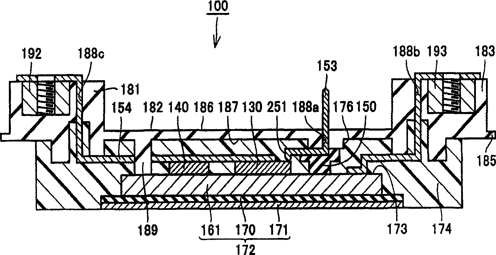
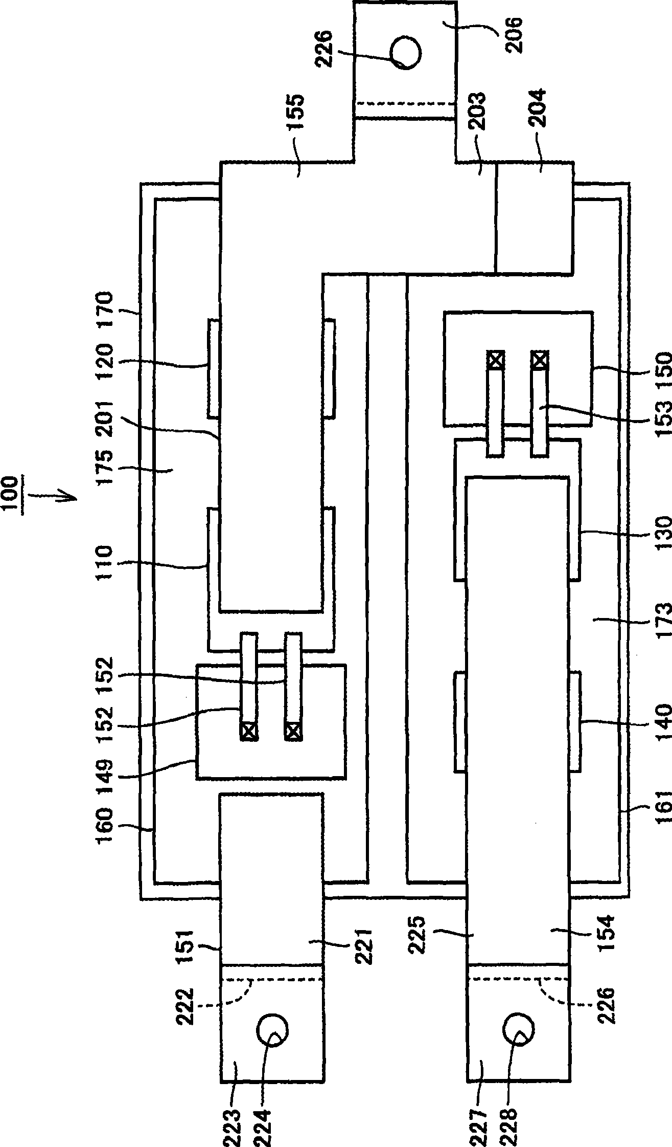
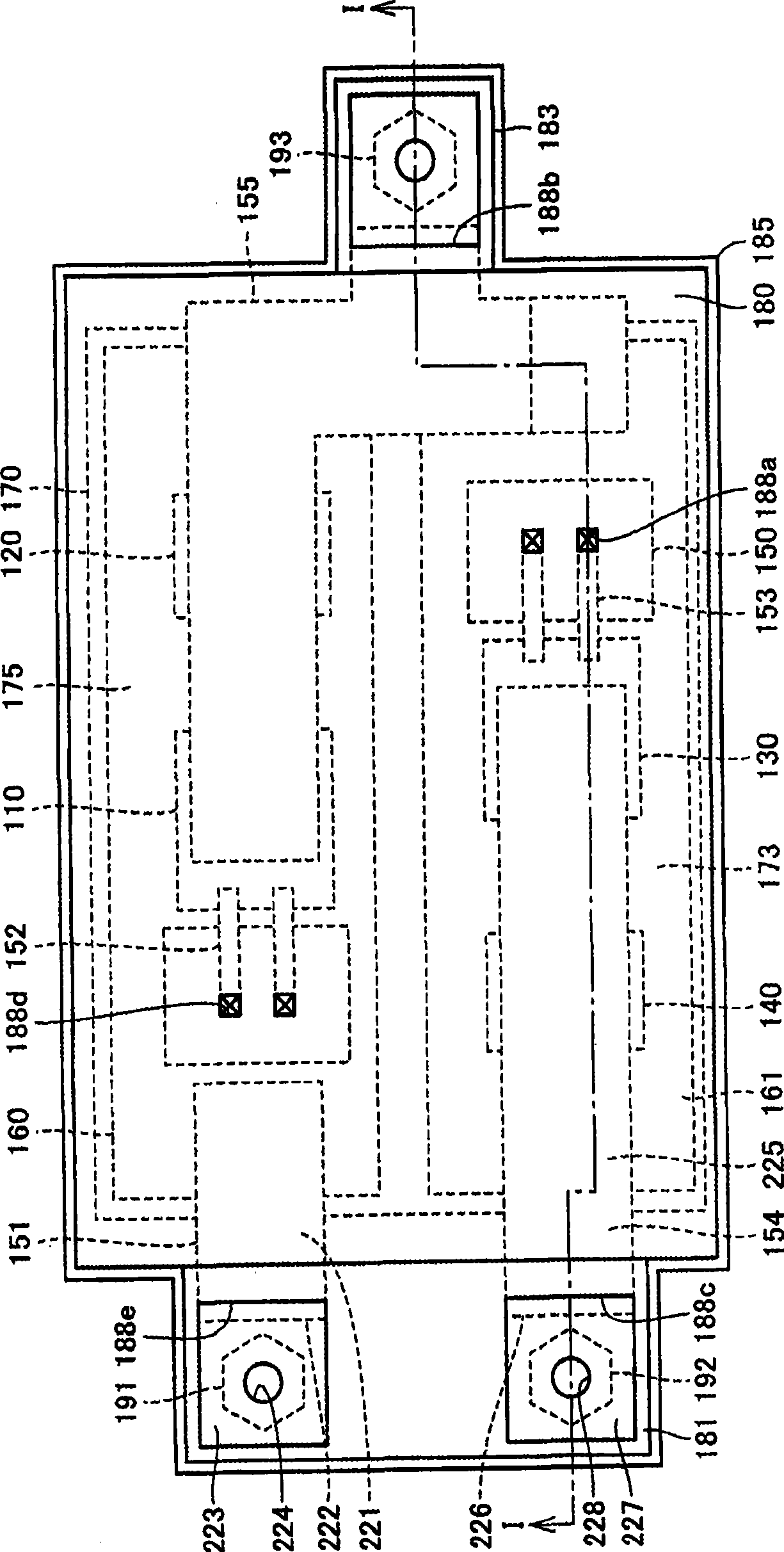
[0069] figure 1 It is a cross-sectional view of the semiconductor device 100 according to the embodiment of the present invention. figure 2 yes figure 1 A plan view of semiconductor device 100 is shown. image 3 It is a plan view of semiconductor device 100 omitting terminal block 182 and molding resin 174 .

[0070] 0030

[0071] exist figure 1 , figure 2 and image 3 In the illustrated example, the semiconductor device 100 is provided with a substrate 172 having a main surface 173; a plurality of elements 110, 120, 130, 140 disposed on the main surface 173 of the substrate 172; 130 , 140 formed on the molding resin 174 ; and the terminal block 182 covering the upper surface of the molding resin 174 .

[0072] 0031

[0073] The elements 110 , 120 , 130 , and 140 are, f...


PUM


Abstract

The present invention provides a semiconductor device and manufacturing method of the same, the method includes steps of: preparing a substrate (172), a clintheriform terminal stand (182) arranged in interval with the substrate (172) to form through holes from a side to the other, and a control terminal (153) built in the through holes and projecting from the terminal stand (182); preparing a first and second metal moulds, the former forming a first concave section of the first metal mould for containing the substrate (172), and the latter forming a second concave section of the second metal mould for containing the terminal stand (182) and a third concave section of the second metal mould for containing the control terminal (153) projecting from the terminal stand (182); configuring the substrate (172) in the first concave section; configuring the terminal stand (182) in the second concave section and configuring the control terminal (153) in the third concave section, and sealing opening of the second concave section of the stand (182); filling resin between the substrate (172) and the terminal stand (182) to form mould resin (174) on the substrate (172) in state that the first and second metal moulds clamping the periphery of the terminal stand (182).

Description

technical field [0001] 0001 [0002] The present invention relates to a semiconductor device and a method of manufacturing the semiconductor device, and more particularly to a semiconductor device in which elements on a substrate are covered with a resin and a method of manufacturing the semiconductor device. Background technique [0003] 0002 [0004] Conventionally, semiconductor devices processed in various ways have been proposed. For example, the electronic circuit device described in JP-A-07-022722 includes: an electronic circuit substrate; electronic components mounted on the electronic circuit substrate; Bonded into one protective resin. The protective resin is composed of a thermosetting resin material mixed with epoxy resin mixed with inorganic powder and a curing agent to cure the resin body, and it is difficult to elastically deform easily. [0005] 0003 [0006] The electrical / electronic module described in JP-A-2004-111435 has an electronic circuit substra...

Claims


Application Information

Patent Timeline
Patent Type & Authority Applications(China)
IPC IPC(8): H01L21/50H01L21/56H01L23/488H01L23/31
CPCH01L23/3107H01L21/565H01L2924/13055H01L2924/0002H01L2224/40137H01L2924/00
Inventor 筱原利彰
Owner MITSUBISHI ELECTRIC CORP
Learn More