
Method for manufacturing light-emitting dioxide having thermally and electrically conductive substrate and structure thereof

A light-emitting diode, electric conduction and heat conduction technology, which is applied in the direction of circuits, electrical components, semiconductor devices, etc., can solve the problems of manufacturing methods and products without methods and structures, increase the production cost of light-emitting diodes, poor heat conduction, etc., and achieve product structure improvement and stability The effect of light quality and technological progress

Inactive Publication Date: 2009-09-02
钜亨电子材料元件有限公司
View PDF1 Cites 7 Cited by
  • Summary
  • Abstract
  • Description
  • Claims
  • Application Information

AI Technical Summary

Problems solved by technology

[0004] The above-mentioned previous proposal uses a metal permanent substrate to replace the sapphire substrate to improve the problem of poor thermal conductivity and achieve antistatic effects. However, the metal permanent substrate is made of metal materials, which can help heat conduction, but it also improves the performance of LEDs. production cost
[0005] It can be seen that the above-mentioned existing manufacturing method for forming a light-emitting diode with a metal substrate obviously still has inconveniences and defects in the manufacturing method, product structure and use, and needs to be further improved urgently.
In order to solve the above-mentioned problems, the relevant manufacturers have tried their best to find a solution, but no suitable design has been developed for a long time, and there is no suitable method and structure for general manufacturing methods and products to solve the above-mentioned problems. , this is obviously a problem that relevant industry players are eager to solve

Method used


Image

  • Method for manufacturing light-emitting dioxide having thermally and electrically conductive substrate and structure thereof
  • Method for manufacturing light-emitting dioxide having thermally and electrically conductive substrate and structure thereof
  • Method for manufacturing light-emitting dioxide having thermally and electrically conductive substrate and structure thereof

Examples


Embodiment Construction

[0057] In order to further explain the technical means and effects of the present invention to achieve the intended purpose of the invention, the light-emitting diode manufacturing method and its structure proposed according to the present invention will be described in detail in conjunction with the accompanying drawings and preferred embodiments. Embodiments, manufacturing methods, steps, structures, features and effects thereof are described in detail below.

[0058] The aforementioned and other technical contents, features and effects of the present invention will be clearly presented in the following detailed description of the preferred embodiments with reference to the drawings. Through the description of the specific implementation mode, a more in-depth and specific understanding of the technical means and effects adopted by the present invention to achieve the intended purpose can be obtained. However, the accompanying drawings are only for reference and description, a...


PUM


Abstract

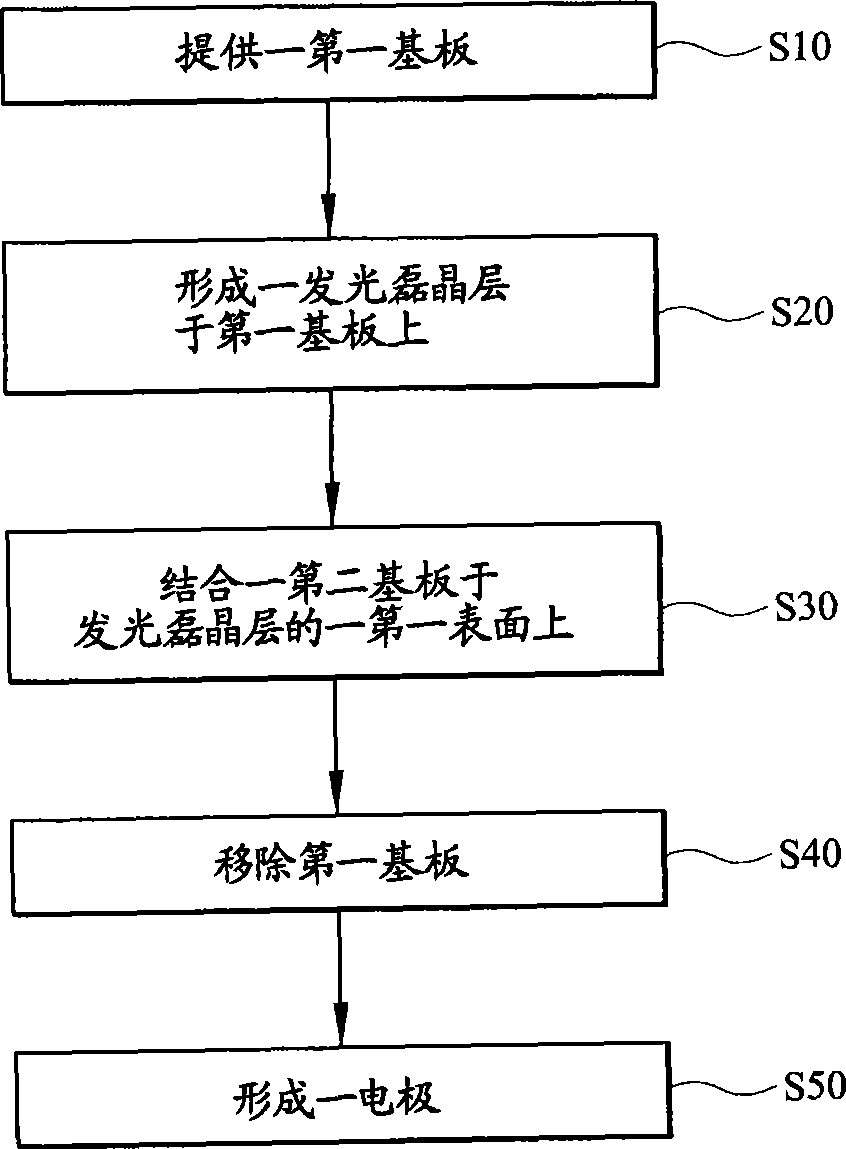
The invention relates to a method for manufacturing a light-emitting dioxide having a thermally and electrically conductive substrate and a structure thereof. The manufacturing method comprises the following steps of: providing a first substrate; forming a light emitting epitaxial layer on the first substrate; combining a second substrate on a first surface of the light emitting epitaxial layer; removing the first substrate; and forming an electrode. The structure of the light-emitting dioxide having the thermally and electrically conductive substrate comprises the second substrate, the light emitting epitaxial layer and the electrode. A used thermally conducive and insulating substrate material with high thermal conductivity allows the heat generated by the light-emitting dioxide during light emission to be discharged effectively to stabilize the quality of emitted light; and a used nonmetal thermally conductive and insulating substrate material results in the reduction of the manufacturing cost of the light-emitting dioxide.

Description

technical field [0001] The invention relates to a method for manufacturing a light-emitting diode with a conductive and heat-conducting substrate and its structure, in particular to a method for manufacturing a light-emitting diode with a conductive and heat-conducting substrate and its structure. Background technique [0002] In conventional light-emitting diodes using sapphire substrates, the heat generated by the light-emitting diodes cannot be effectively removed due to the poor thermal conductivity of the sapphire substrates, which reduces the light-emitting efficiency of the light-emitting diodes and shortens the service life of the light-emitting diodes. Moreover, the sapphire substrate has a non-conductive characteristic, so the problem of static electricity accumulation is prone to occur. [0003] As disclosed in Taiwan Patent No. I224876 "Manufacturing Method for Forming a Light Emitting Diode with a Metal Substrate", it includes the following steps: providing a te...

Claims


Application Information

Patent Timeline
IPC IPC(8): H01L33/00
Inventor 张旭源
Owner 钜亨电子材料元件有限公司
Learn More