Small-angle white light source

A white light source, small angle technology, applied in the field of white light source, can solve the problems of short projection distance, backward technology, complicated process, etc., to achieve the effect of short projection distance, increased intensity and projection distance, and complex process

Pending Publication Date: 2018-04-03
广东中晶激光照明技术有限公司
View PDF10 Cites 4 Cited by
  • Summary
  • Abstract
  • Description
  • Claims
  • Application Information

AI Technical Summary

Problems solved by technology

[0003] In order to overcome the disadvantages of backward technology, complex process, low efficiency, scattered light source, weak intensity and short projection distance caused by the use of LED or RGB or color chips in laser lighting for the existing traditional light source lighting components , the present invention provides a small-angle white light source, which has the advantages of simple process, high luminous efficiency, small light source emission angle, concentrated light source, strong intensity, and long projection distance

Method used


Image

  • Small-angle white light source
  • Small-angle white light source
  • Small-angle white light source

Examples


Embodiment 1

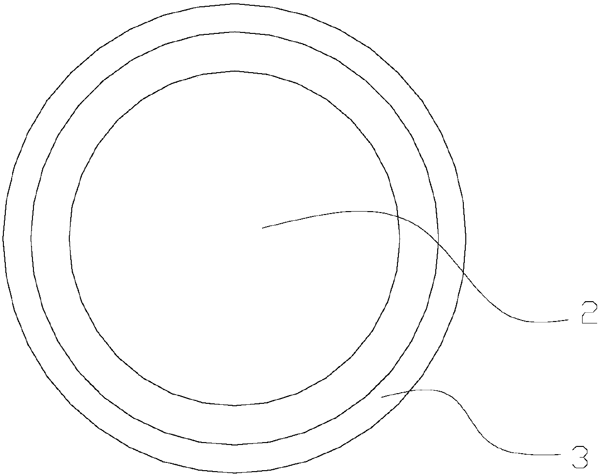
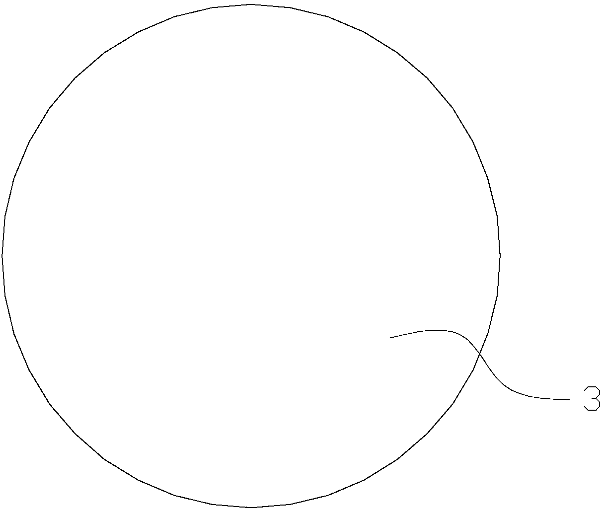
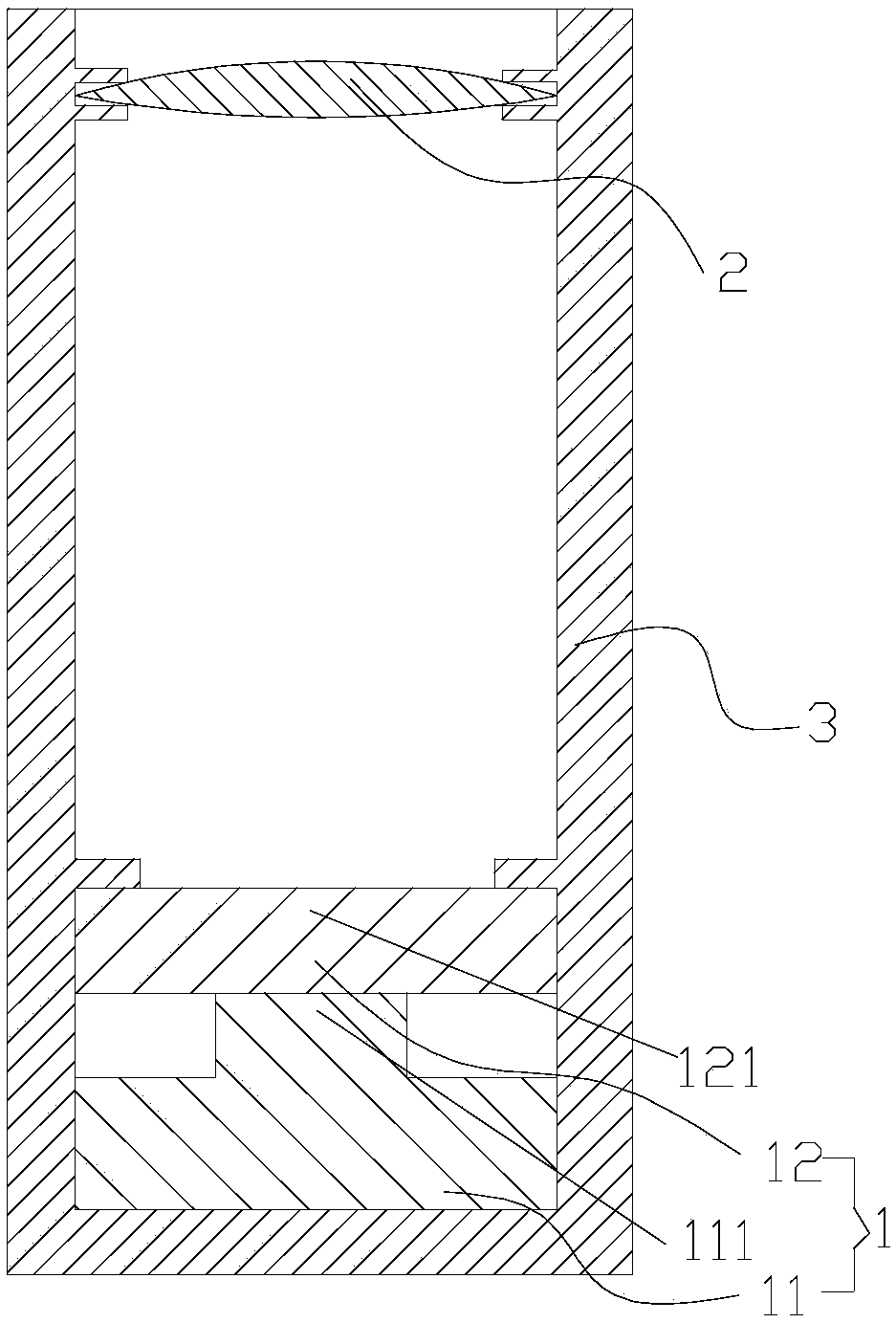
[0048] Such as Figure 1-3As shown, a small-angle white light source according to the present invention includes a laser white light source 1 and a collimator lens 2 arranged directly above the light output end of the laser white light source 1, and the laser white light source 1 includes a blue laser emitting device 11 and a light conversion medium 12, the light conversion medium 12 is arranged on the surface of the laser output end 111 of the blue laser emitting device 11; the blue laser emitted by the blue light laser emitting device 11 is excited and converted into white light after passing through the light conversion medium 12, and the white light The collimated lens 2 is collected into small-angle white light. The small-angle white light source also includes a hollow and long cylindrical cavity 3 with an open top, and the collimator lens 2 and the laser white light source 1 are respectively fixed at the upper and lower ends of the cavity 3 . The laser white light sourc...

Embodiment 2

[0050] Such as Figure 4 As shown, the difference from Embodiment 1 is that the light conversion medium 12 is fixed on the surface of the laser emitting end 111 of the blue laser emitting device 11 by the fixing device 13 . The laser emitting end 111 of the blue laser emitting device 11 is embedded in the light converting medium 12 .

Embodiment 3

[0052] Such as Figure 5-7 As shown, the difference from Embodiment 1 is that: the shape of the light exit surface 121 of the light conversion medium 12 is a conical surface, wherein the exit angle of the conical surface is 1-150°. The bottom of the cavity 3 is open, and the blue-ray laser emitting device 11 is an in-line blue-ray laser emitting device. The upper surface of the in-line blue-ray laser emitting device is a laser emitting end 111, and a pin 112 is provided on the lower surface. The pin 112 protrudes from the opening at the bottom of the cavity 3 . The in-line blue-ray laser emission device is a blue-ray laser light source packaged in TO form.


PUM


Abstract

The invention relates to a small-angle white light source which comprises a laser white light source and a collimating lens arranged right above the light-emitting end of the laser white light source,wherein the laser white light source comprises a blue light laser transmitting device and a light conversion medium; the light conversion medium is arranged on the surface of the laser emitting end of the blue light laser transmitting device; the blue light laser transmitted by the blue light laser transmitting device pass through the light conversion medium to be activated and converted into white light; and the white light is gathered into small-angle white light by the collimating lens. The small-angle white light source overcomes the defects that the technology is outdated, the techniqueis complicated, the efficiency is low, the light source is disperse, intensity is weak, and the projection distance is short because the light-emitting component of the existing traditional light source adopts LEDs or the manner of RGE or color chips in laser lighting and has the advantages of being in simple in technique, high in light-emitting efficiency, small in light source emitting angle, centralized in light source, high in intensity and long in projection distance.

Description

technical field [0001] The invention relates to a small-angle white light source, which is applied in the lighting field. Background technique [0002] At present, the most advanced technology used in the field of lighting is LED lighting. Compared with traditional incandescent lamps and energy-saving lamps, LED lighting can save 50-70% of electricity; and laser lighting, as the next-generation lighting technology of LED, can save 50-50% of electricity compared with LED. 80%, will become the replacement product of LED. Most of the existing light source light-emitting components use LEDs or RGB or color chips (color wheels) in laser lighting. The technology is backward, the process is complicated, and the efficiency is low, and the light source output angle is large, the light source is scattered, The intensity is weak and the projection distance is short, so it is difficult to meet the needs of special lighting. Therefore, it has become an urgent task to provide a small-an...

Claims


Application Information

Patent Timeline
Patent Type & Authority Applications(China)
IPC IPC(8): F21S10/02F21V5/04F21V19/00F21Y115/10
CPCF21S10/02F21V5/04F21V19/00F21Y2101/00
Inventor 夏泽强程世望张云鸿
Owner 广东中晶激光照明技术有限公司
Why Eureka
Try Eureka