
Self-shunt excitation system based on parallel-connection multiple-voltage type convertor

An excitation system and voltage-type technology, applied in the direction of synchronous generators, etc., can solve problems such as system accident expansion and insufficient excitation capacity, and achieve good excitation capacity, harmonic reduction, and small harmonic effects

Active Publication Date: 2011-04-20
HUAZHONG UNIV OF SCI & TECH
View PDF0 Cites 0 Cited by
  • Summary
  • Abstract
  • Description
  • Claims
  • Application Information

AI Technical Summary

Problems solved by technology

Once the excitation capacity is insufficient, it will inevitably lead to the expansion of system accidents

Method used


Image

  • Self-shunt excitation system based on parallel-connection multiple-voltage type convertor
  • Self-shunt excitation system based on parallel-connection multiple-voltage type convertor
  • Self-shunt excitation system based on parallel-connection multiple-voltage type convertor

Examples


Embodiment Construction

[0018] Below in conjunction with accompanying drawing and example the present invention is described in further detail.

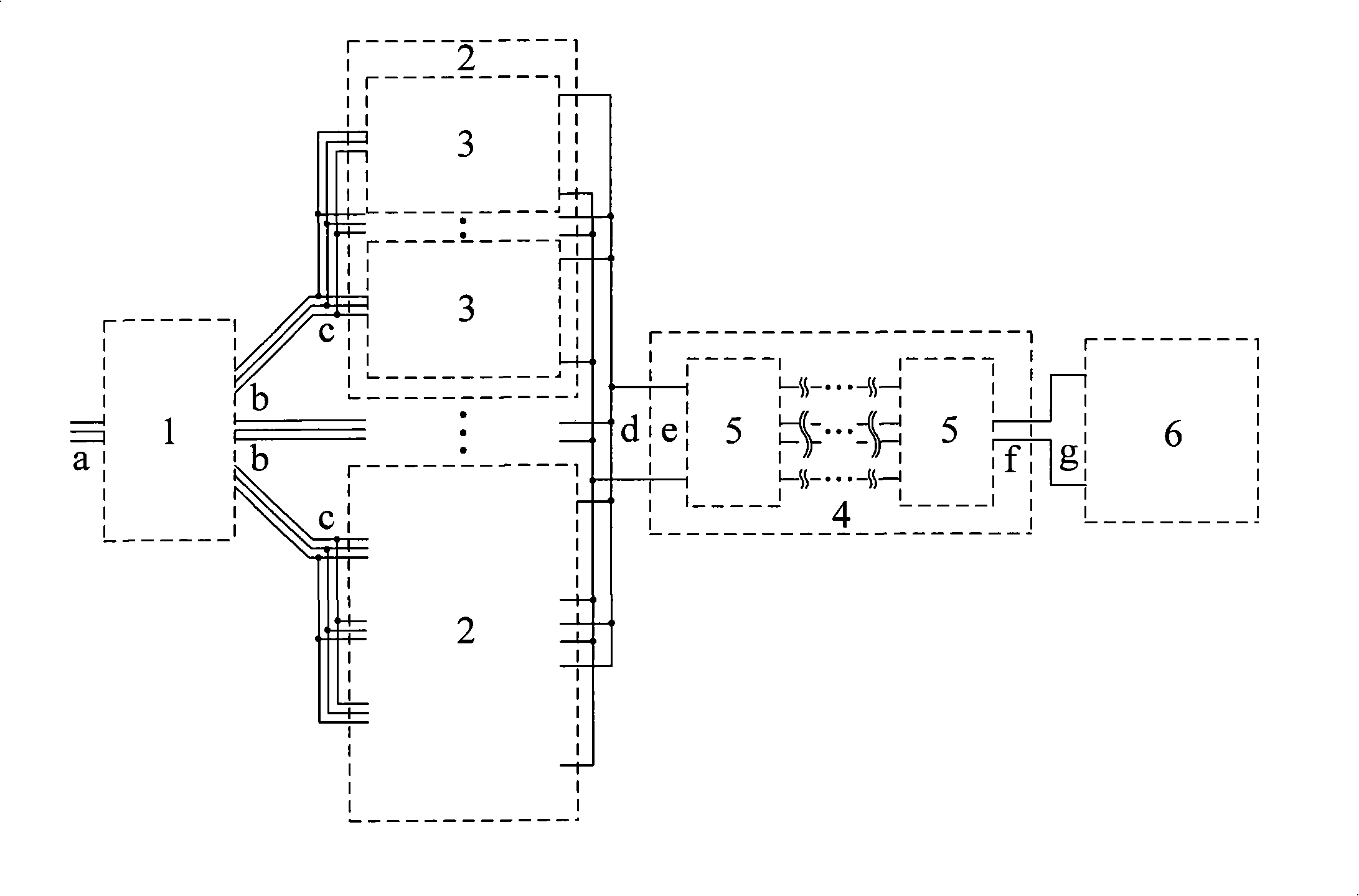
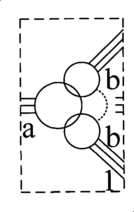
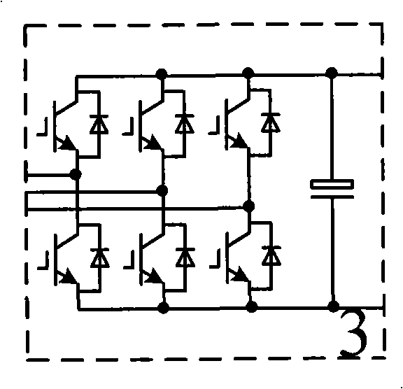
[0019] like figure 1 A structural schematic diagram of an embodiment of the present invention. The system includes an excitation transformer 1 (such as figure 2 shown), M voltage-source converters 2, chopper parallel groups 4 and excitation coils 6 (such as Figure 5 shown); the number of primary windings of excitation transformer 1 is 1, the number of secondary windings is M, and M≥1; the primary winding a of excitation transformer 1 is connected to the machine terminal of the synchronous generator; the number of M voltage-type converters 2 The AC port c is connected to the M secondary windings b of the excitation transformer 1 in one-to-one correspondence; the DC ports of the M voltage source converters 2 are connected in parallel to form a DC port d, which is connected to a port e of the chopper parallel group 4 The other port f of the chopper parall...


PUM


Abstract

The invention provides a self-shunt excitation system based on a parallel-connection multiple-voltage type convertor, which comprises an exciting transformer, M voltage type convertors, a chopper paraThe invention provides a self-shunt excitation system based on a parallel-connection multiple-voltage type convertor, which comprises an exciting transformer, M voltage type convertors, a chopper parallel component and an exciting coil, wherein the number of the primary winding of the exciting transformer is one, the number of the secondary windings of the exciting transformer is M, and the M is mllel component and an exciting coil, wherein the number of the primary winding of the exciting transformer is one, the number of the secondary windings of the exciting transformer is M, and the M is more than or equal to 1; and the alternating-current terminals of the M voltage type convertors are connected with the M secondary windings of the exciting transformer in a one-to-one correspondence waore than or equal to 1; and the alternating-current terminals of the M voltage type convertors are connected with the M secondary windings of the exciting transformer in a one-to-one correspondence way, and the direct-current terminals of the M voltage type convertors are connected in parallel to form direct-current ports connected with one port of the chopper parallel component, the exciting coily, and the direct-current terminals of the M voltage type convertors are connected in parallel to form direct-current ports connected with one port of the chopper parallel component, the exciting coil is connected at the other port of the chopper parallel component, and each voltage type convertor is formed by at least one voltage type three-phase fully-controlled bridge circuit in a parallel connis connected at the other port of the chopper parallel component, and each voltage type convertor is formed by at least one voltage type three-phase fully-controlled bridge circuit in a parallel connection way. The invention not only can provide damping for the system through a direct-current exciter, but also can provide damping by regulating the terminal voltage of the synchronous generator, thection way. The invention not only can provide damping for the system through a direct-current exciter, but also can provide damping by regulating the terminal voltage of the synchronous generator, thereby effectively inhibiting the low / ultralow frequency oscillation of the electric power system and enhancing the running stability of the electric power system.ereby effectively inhibiting the low / ultralow frequency oscillation of the electric power system and enhancing the running stability of the electric power system.

Description

technical field [0001] The invention relates to the field of excitation control systems, in particular to a voltage-type converter-based self-shunt excitation control system. Background technique [0002] Modern power systems require that the excitation system of synchronous generators can suppress low-frequency / ultra-low-frequency oscillations of 0.1Hz to 3Hz. However, the excitation system of conventional silicon controlled rectifiers only enhances damping by controlling DC excitation, and it is difficult to achieve the purpose of suppressing low-frequency oscillations in a wide range from low-end 0.1Hz to high-end 3Hz. When low-frequency / ultra-low-frequency oscillation occurs in the power grid, the terminal voltage of the synchronous generator will also oscillate with a large low-frequency / ultra-low frequency, so that the terminal voltage may continue to be at a low level for a long time (several seconds). During oscillation, if a short-circuit fault occurs in the system...

Claims


Application Information

Patent Timeline
Patent Type & Authority Patents(China)
IPC IPC(8): H02K19/26
Inventor 毛承雄陆继明王丹娄慧波何丽娜张坤杨嘉伟刘海波
Owner HUAZHONG UNIV OF SCI & TECH
Learn More