Cuff for sphygmomanometer and sphygmomanometer

A sphygmomanometer and cuff technology, applied in the field of sphygmomanometers, can solve problems such as folds of 162 of the inner peripheral side panel, achieve the effects of stable pressure, prevent internal bleeding, and protect fluid bags

Active Publication Date: 2009-09-02
OMRON HEALTHCARE CO LTD
View PDF6 Cites 10 Cited by
  • Summary
  • Abstract
  • Description
  • Claims
  • Application Information

AI Technical Summary

Problems solved by technology

When the above-mentioned frictional force is weak, the inner peripheral side sheet portion 162 of the cover body 161 will not follow the fold S portion on the inner side sheet 152 of the air bag 151, but at this time the diameter of the inner peripheral side sheet portion 162 of the cover body 161 will still change. As the air bag 151 expands and contracts, an excess portion is generated on the inner peripheral side panel portion 162 of the cover body 161 .
Accordingly, the excess portion enters the valley portion where wrinkles S are formed on the pressing surface 152 a of the air bag 151 , causing wrinkles to also occur on the inner peripheral side panel portion 162 .

Method used


Image

  • Cuff for sphygmomanometer and sphygmomanometer
  • Cuff for sphygmomanometer and sphygmomanometer
  • Cuff for sphygmomanometer and sphygmomanometer

Examples


no. 1 approach

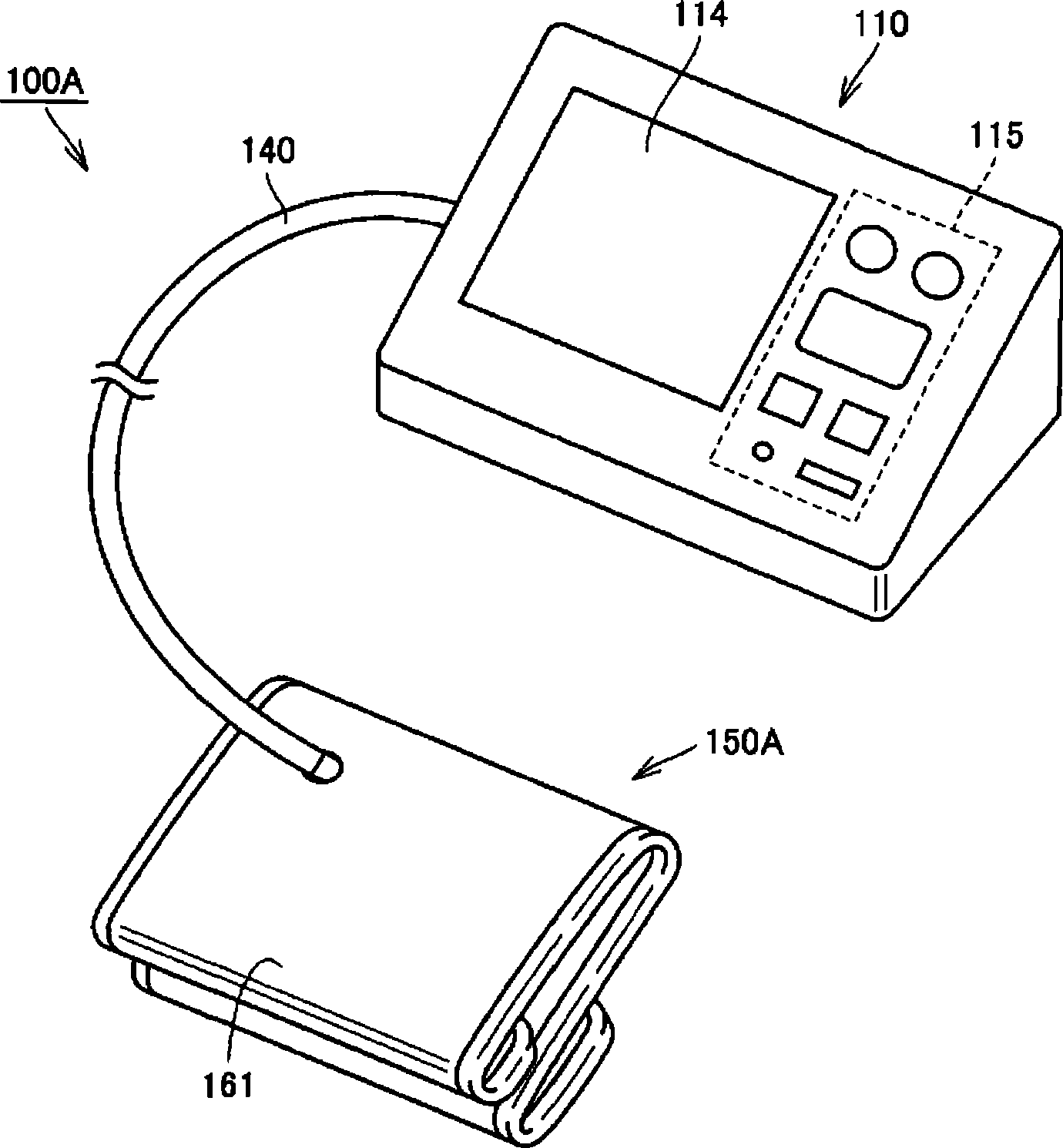
[0071] figure 1 It is a perspective view showing the appearance of the sphygmomanometer according to the first embodiment of the present invention. First, refer to figure 1 , the appearance structure of the sphygmomanometer of this embodiment will be described.

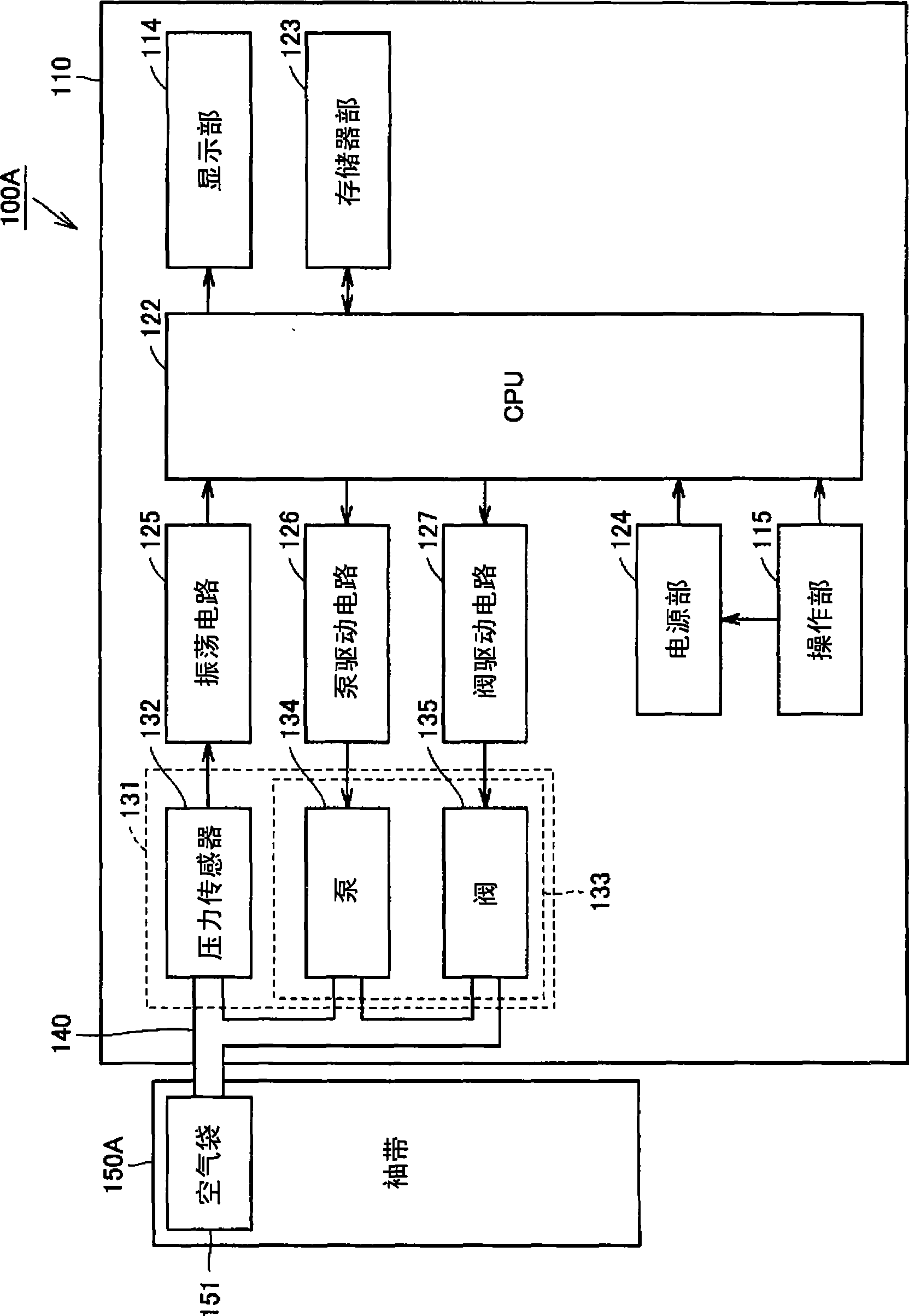
[0072] Such as figure 1 As shown, the sphygmomanometer 100A of this embodiment mainly includes a device main body 110 and a cuff 150A. The device main body 110 has a display unit 114 and an operation unit 115 . The display unit 114 displays the measurement results of the blood pressure value, the measurement results of the pulse rate, and the like in a visually recognizable manner using numerical values, graphs, and the like. As the display unit 114, for example, a liquid crystal panel or the like is used. The operation unit 115 is provided with, for example, a power switch, a measurement start switch, and the like.

[0073] The purpose of using the cuff 150A is to wrap the cuff 150A around the upper arm of t...

no. 2 approach

[0117] Figure 16 and Figure 17 It is a perspective view showing the appearance structure of the sphygmomanometer according to the second embodiment of the present invention. in addition, Figure 18 and Figure 19 It is a cross-sectional view of the blood pressure monitor cuff according to the present embodiment. here, Figure 19 The cross-section of the blood pressure cuff shown is along the Figure 18 The cross-sectional view of the line XIX-XIX shown. In addition, since the functional blocks and measurement flow of the blood pressure monitor 100B of this embodiment are based on the blood pressure monitor 100A of the first embodiment described above, description thereof will not be repeated here.

[0118] First, refer to Figure 16 and Figure 17 , the appearance structure of the sphygmomanometer of this embodiment will be described. Such as Figure 16 and Figure 17 As shown, the sphygmomanometer 100B of this embodiment mainly includes: the device main body 110,...


PUM


Abstract

A cuff (150A) for sphygmomanometers wrapped around the upper arm (200) of a user for use comprises an air bag (151), a cover body (161), and a cushion member (171). The air bag (151) inflated or contracted by flowing a fluid therein and thereout has a press acting surface (152a) positioned on the upper arm (200) side when the cuff (150A) is wrapped around the upper arm (200). The cover body (161) enclosing the air bag has an inner sheet part (162) positioned on the upper arm (200) side when the cuff (150A) is wrapped around the upper arm (200). The cushion member (171) is positioned on the inner sheet part (162) inside the press acting surface (152a), and can be compressed in the direction parallel to the thickness direction of the inner sheet part (162). With this constitution, internal bleeding under a portion to be measured which may occur during the measurement of the blood pressure can be surely prevented from occurring.

Description

technical field [0001] The present invention relates to a cuff for a sphygmomanometer used for wrapping around a site to be measured in a living body such as a wrist or an upper arm when measuring blood pressure, and a sphygmomanometer having the cuff. Background technique [0002] Generally, when measuring blood pressure, a cuff is wrapped around the body surface of a living body, and the fluid bag is inflated and contracted to detect the arterial pressure pulse wave generated in the artery, thereby measuring the blood pressure. The band has a built-in fluid bag for compressing the arteries inside the living body. Here, the cuff refers to a belt-shaped structure having a lumen, which can be wound around a part of a living body, and fluid such as gas or liquid is injected into the lumen to measure arterial pressure of the upper and lower limbs. Therefore, a cuff is a term that refers to a concept including a fluid bag and a winding member for wrapping the fluid bag around a...

Claims


Application Information

Patent Timeline
Patent Type & Authority Applications(China)
IPC IPC(8): A61B5/022
CPCA61B5/02233
Inventor 高桥明久大西喜英茎田知宏上坂知里泽野井幸哉柳濑真孝
Owner OMRON HEALTHCARE CO LTD
Why Eureka
Try Eureka