Coupling device

A coupling and axial technology, which is applied in the direction of couplings, elastic couplings, machines/engines, etc., can solve the problem of impossible installation space, etc., and achieve low manufacturing tolerance, easy manufacturing, and easy axial displacement Effect

Inactive Publication Date: 2009-09-02
PIERBURG GMBH & CO KG NEUSS
View PDF1 Cites 7 Cited by
  • Summary
  • Abstract
  • Description
  • Claims
  • Application Information

AI Technical Summary

Problems solved by technology

[0005] However, the known embodiment suffers from the disadvantage that under today's extremely demanding space conditions in the

Method used


Image

  • Coupling device

Examples


Embodiment Construction

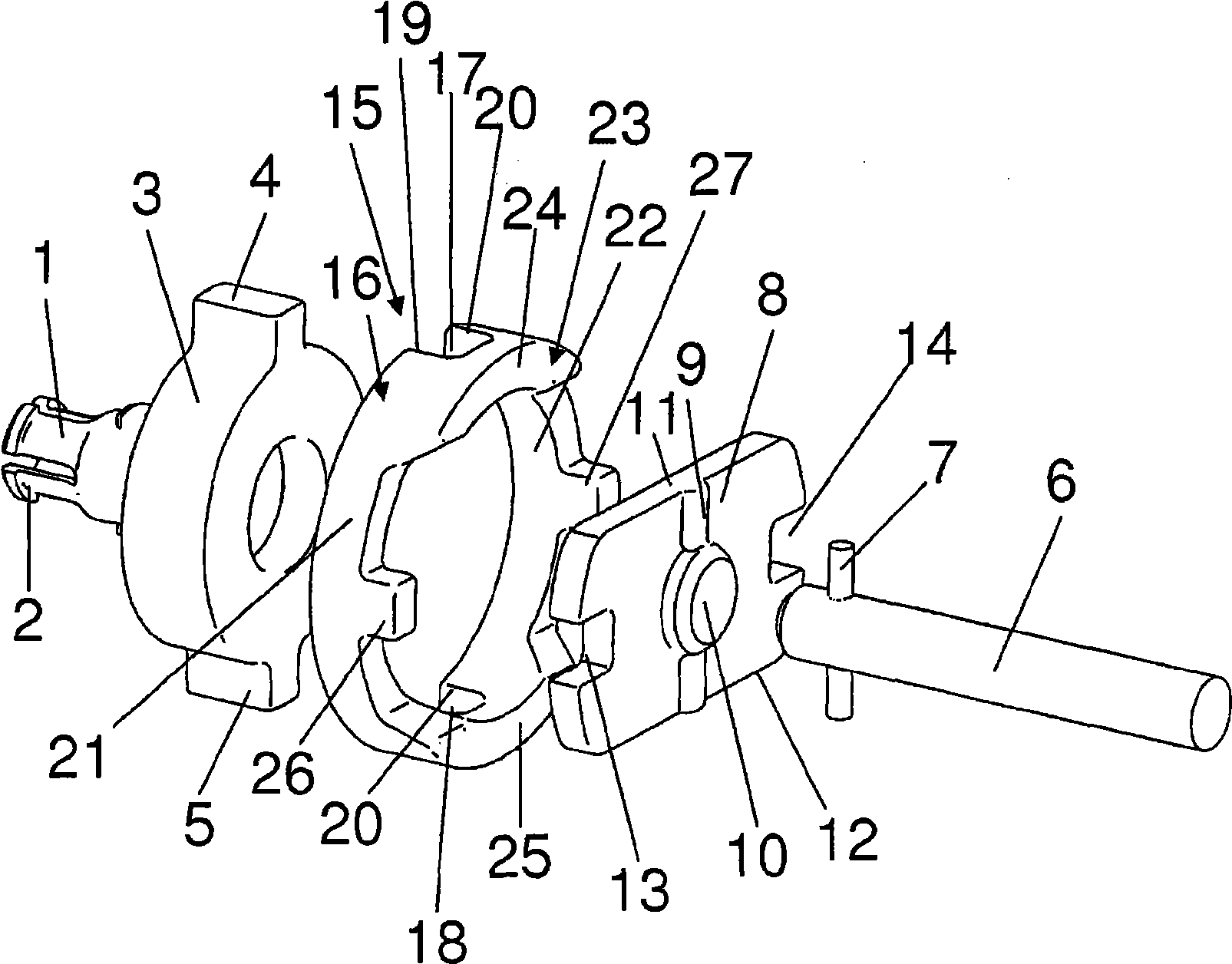
[0017] The coupling of the invention shown in the figures comprises a first shaft 1, which in this embodiment is formed as a shaft stub, which can be connected, for example via a clip connection, to a shaft of an actuating device. Correspondingly shaped output shaft.

[0018] The shaft 1 comprises an end section 3 which is considerably widened compared to the shaft diameter and which comprises two radially outward projections 4 , 5 . Apart from the protrusions, the end section 3 is shaped as a short cylindrical body. Arranged substantially opposite the first shaft 1 is a second shaft 6 having a pin 7 extending radially through the second shaft 6 for establishing a connection to an end section 8 for rotation therewith. A groove 9 and a through hole 10 corresponding to the pin 7 are provided for connecting the second shaft 6 to the end section 8 . Of course, it is also possible to manufacture the shaft integrally with said second end section 8 or to injection mold the end sect...


PUM


Abstract

It is known that two shafts can be connected via Oldham couplings. According to the invention, a coupling device is proposed, wherein recesses (13, 14) and projections (4, 5) of end sections (3, 8) of the shafts (1, 6) extend radially and a coupling member (15) substantially surrounds the two end sections (3, 8) of the two shafts (1, 6), wherein both end sections (3, 8) lie directly opposite each other. Accordingly, corresponding projections (26, 27) and recesses (17, 18) are provided on the coupling member (15) for the transmission of torque. Such a device reduces the axial installation length of a coupling device of this type.

Description

technical field [0001] The present invention relates to a shaft coupling for transmitting torque from a first shaft to an axially opposite second shaft, the shafts being provided with end sections having formed thereon diametrically opposite, radially extending protrusions and / or grooves, the protrusions and / or grooves are arranged to cooperate with the protrusions and / or grooves of the coupling member, wherein the coupling member corresponds to the end section provided on the first shaft The grooves or protrusions are arranged at an angular displacement of substantially 90° with respect to the grooves or protrusions corresponding to the end section provided on the second shaft. Background technique [0002] This type of coupling, called "Oldham coupling" or "double-loop transmission", is known and described in a number of patent applications. These couplings are known, for example, from the automotive sector, where they are used to couple the output shaft of the actuating ...

Claims


Application Information

Patent Timeline
IPC IPC(8): F16D3/04
CPCF16D3/04F02D9/1065F16D3/00
Inventor 马克-安东·慕尼黑卡斯滕·沃伊特兰德迈克尔·维尔凯特
Owner PIERBURG GMBH & CO KG NEUSS
Why Eureka
Try Eureka