Multifunctional rotary type weeding machine
A rotary and weeding machine technology, applied in the field of weeding machines and multifunctional rotary weeding machines, can solve the problems of high cost, single weeding, complex technical structure, etc., and achieve reliable mechanical operation, adjustable operating speed, and simple overall structure Effect
- Summary
- Abstract
- Description
- Claims
- Application Information
AI Technical Summary
Problems solved by technology
Method used
Image
Examples
Embodiment 1
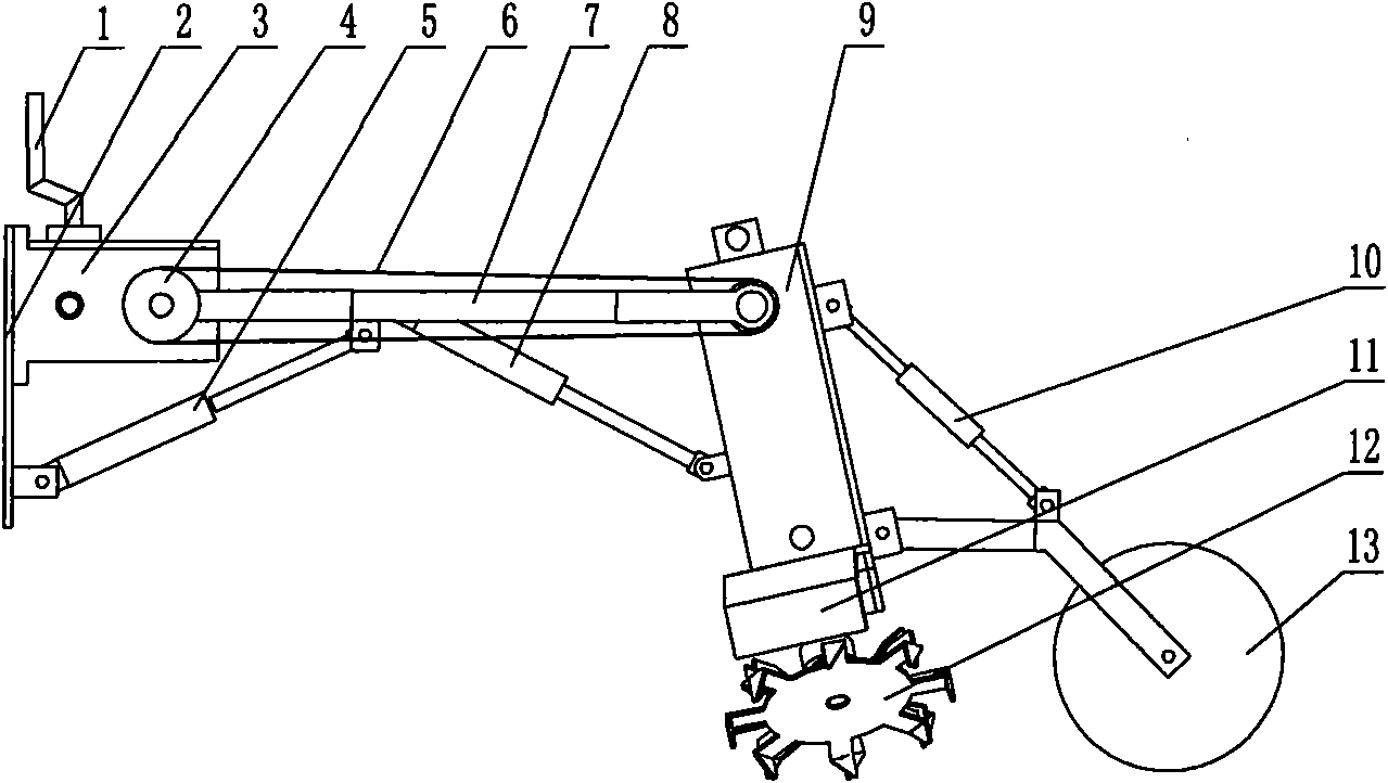
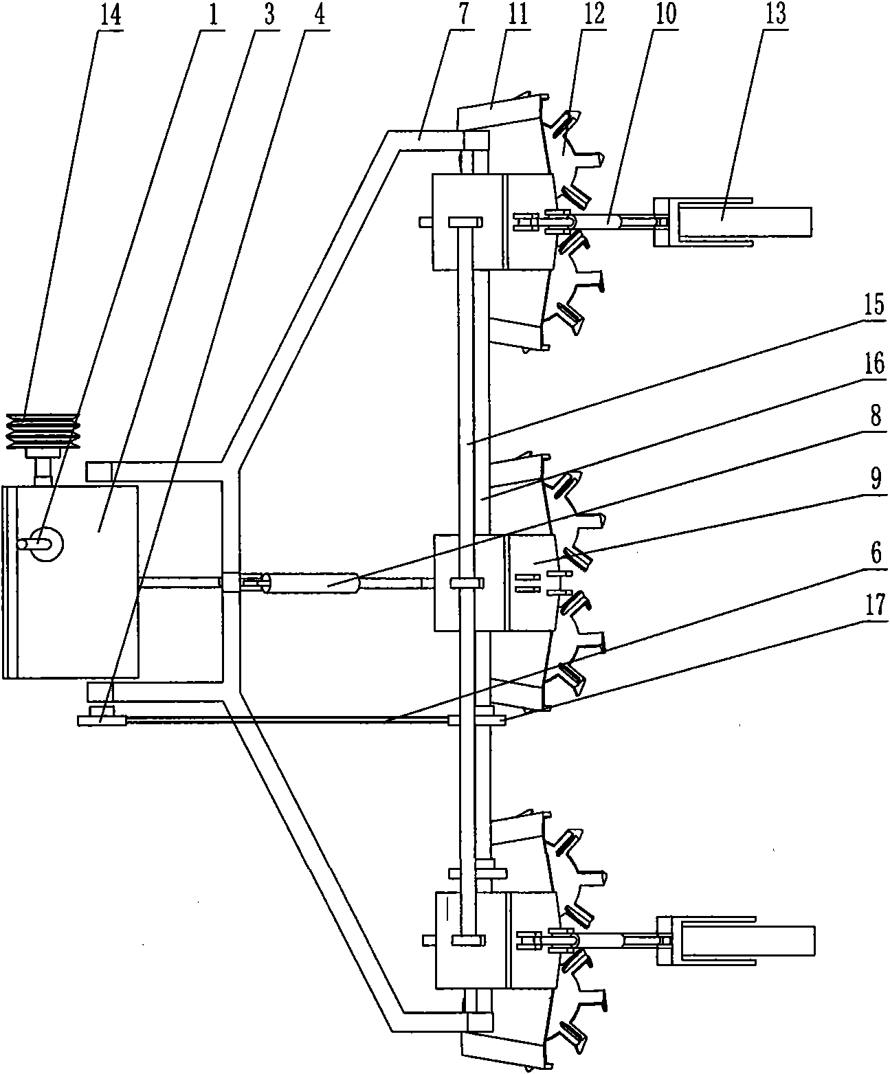
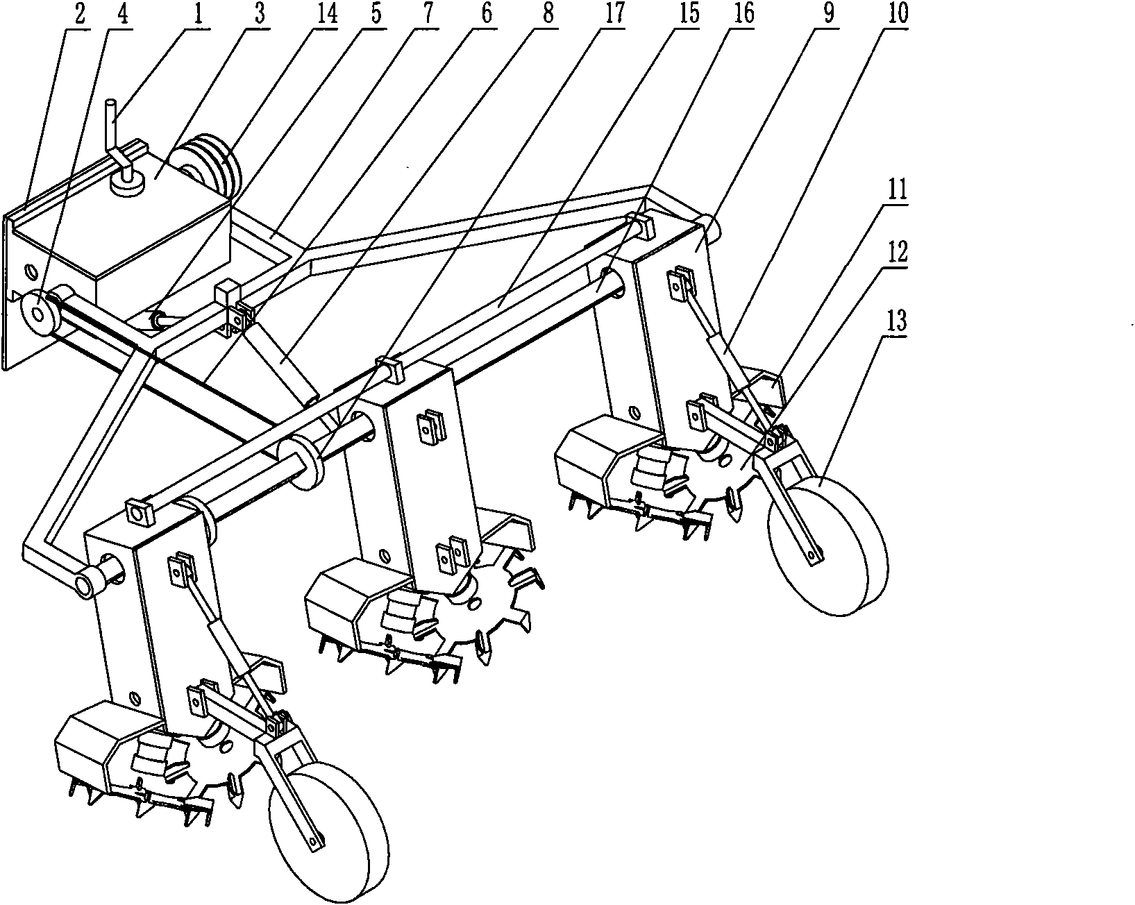
[0028] Embodiment 1: see Figure 1-Figure 4 .
[0029] A multi-functional rotary weeder, its power connection with the tractor is realized by a belt pulley 14, and it is rigidly installed with the tractor through a mounting plate 2. Belt pulley and mounting plate are all installed on the belt pulley transmission case 3, and a speed change lever 1 is also installed on this belt pulley transmission case, and a sprocket wheel 4 is installed by the output shaft after the speed change lever adjustment in the belt transmission case. A frame 7 is horizontally hinged on both sides of the belt drive case, and the lifting of the frame is realized by being installed on the frame by the plunger end of a hydraulic cylinder 5 installed on the mounting plate. An operating system is hinged on the inside of the front end of the frame. The operating system consists of a horizontal frame 15, a drive shaft 16, a reduction box 9, a depth-limiting follower wheel 13, a soil retaining plate 11, and ...
Embodiment 2
[0038] see Figure 5-Figure 8 .
[0039] A multi-functional rotary weeder, its power connection with the tractor is an input shaft 26, and its rigid connection with the tractor adopts a three-point suspension, that is, the connection mode of a horizontal pin 27, a vertical frame 28 and an inclined frame 29, Among them, the inclined frame and the reduction box are connected in a hinged manner. The difference between this structure and Embodiment 1 is that the hydraulic cylinder (marked 5 in the figure) is omitted, and other external structures are the same as Embodiment 1.
[0040] The transmission box and speed reduction mechanism in this embodiment refer to Figure 8 , the specific transmission structure is:
[0041] 1. The transmission structure of the transmission box is:
[0042]The power input shaft adopts bevel gear 30 to be connected with the input shaft of transmission box, and others are the same as embodiment 1.
[0043] 2. The transmission structure of the redu...
PUM
 Abstract
Description
Claims
Application Information
 - R&D
- Intellectual Property
- Life Sciences
- Materials
- Tech Scout
- Unparalleled Data Quality
- Higher Quality Content
- 60% Fewer Hallucinations
Browse by: Latest US Patents, China's latest patents, Technical Efficacy Thesaurus, Application Domain, Technology Topic, Popular Technical Reports.
© 2025 PatSnap. All rights reserved.Legal|Privacy policy|Modern Slavery Act Transparency Statement|Sitemap|About US| Contact US: help@patsnap.com


