Hydraulic-control mold filling device of low-pressure casting lift tube

A technology of low-pressure casting and riser tubes, which is applied in the field of low-pressure casting riser tube mold filling devices, can solve problems such as shrinkage cavities, poor steady-state characteristics, and high prices of products, so as to reduce equipment use costs, improve efficiency, and reduce The effect of equipment cost

Inactive Publication Date: 2011-02-09
SHANGHAI RODDEX BATH HARDWARE
View PDF4 Cites 0 Cited by
  • Summary
  • Abstract
  • Description
  • Claims
  • Application Information

AI Technical Summary

Problems solved by technology

[0002] The pressure-time control of the filling process of the existing low-pressure casting riser pipe adopts an independent air source composed of an air pump, and the dried air is charged into the electric furnace at different pressures according to the shape and size of the casting, so that the furnace The non-ferrous metal molten liquid in the furnace generates pressure on it, and the metal solution rises along the riser pipe at different pressures and speeds and is injected into the metal mold. The disadvantages are: ①The gas injected into the furnace must be dried before it can be injected into the furnace ;② Use expensive imported electric-pneumatic proportional pressure valves to control different pressures in each time period, and complete the pressure and speed control of the entire process of filling, boosting, pressure maintaining, and pressure relief, and due to changes in gas temperature , controlled by an electric-pneumatic proportional valve, its steady-state characteristics are very poor, resulting in shrinkage cavities and porosity defects in the product; ③The filling pressure is low, generally 0.3-0.5Mpa, which will also cause some insufficient filling, Insufficient low-pressure fluid replacement results in waste products

Method used


Image

  • Hydraulic-control mold filling device of low-pressure casting lift tube
  • Hydraulic-control mold filling device of low-pressure casting lift tube

Examples


Embodiment Construction

[0014] The invention will be further described below in conjunction with the accompanying drawings, and the present invention is relatively clear to those skilled in the art.

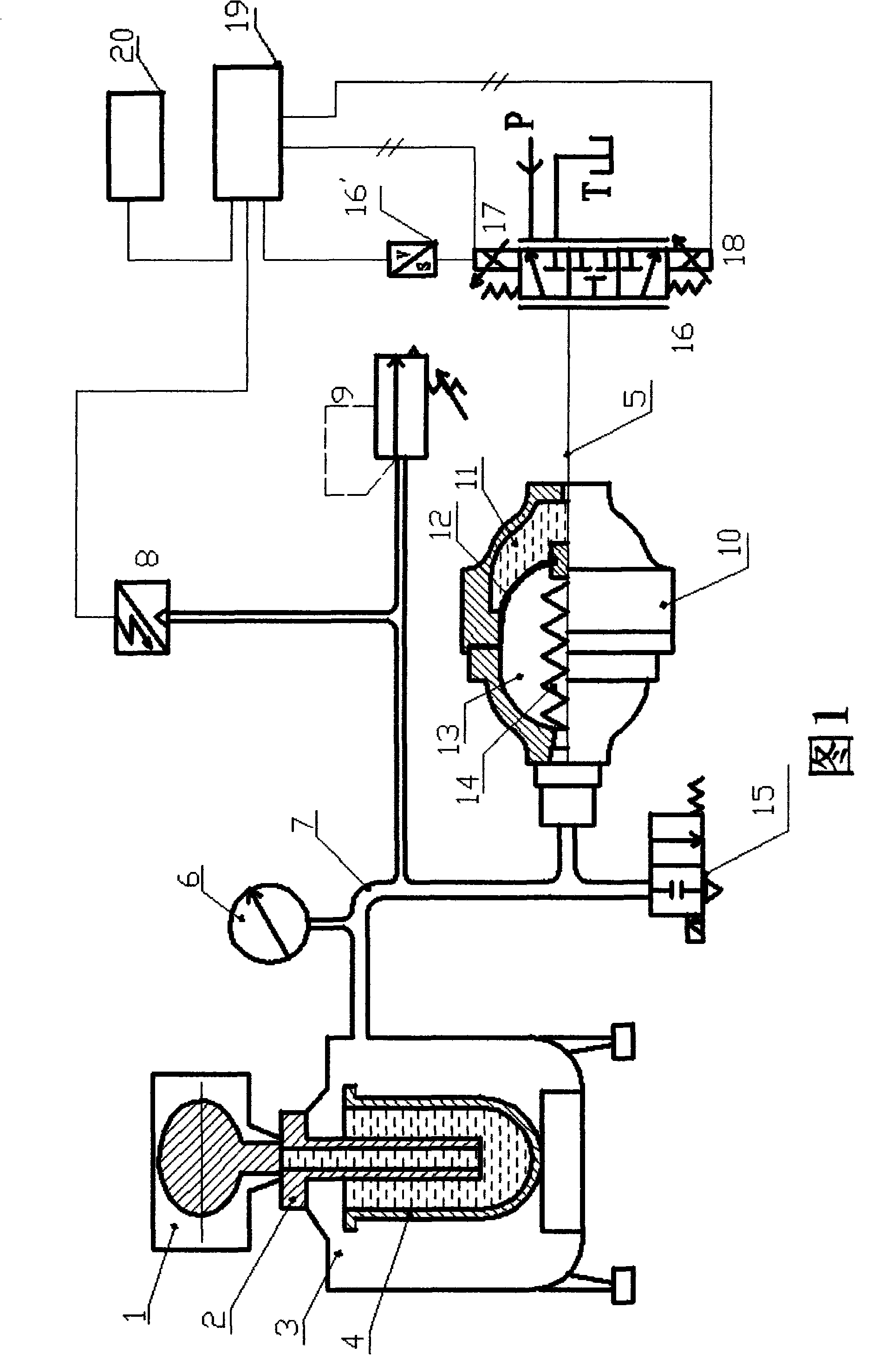
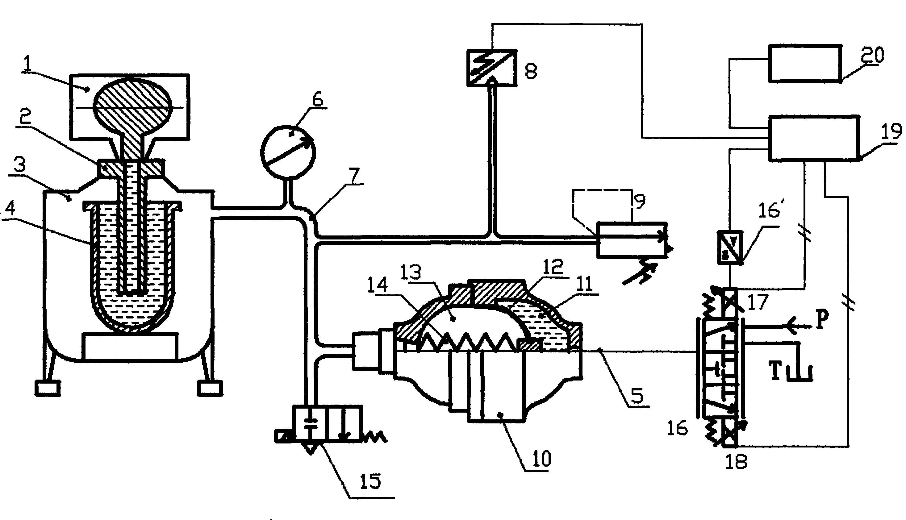
[0015] Prepare the air pressure-time program according to the required process, the program is stored by the PLC controller 20, the PLC controller 20 sends instructions to the power amplifier 19 with feedback signal to drive the proportional electromagnet 17, and the proportional electromagnet 17 drives the three-position electro-hydraulic proportional The spool of the valve 16 moves, so that the single oil port on the left side of the three-position electro-hydraulic proportional valve 16 communicates with the high-pressure hydraulic oil inlet P connected to the one port on the right side of the three-position electro-hydraulic proportional valve 16, and the hydraulic oil in the high-pressure state passes through the seal. The oil pressure tube 5 is filled into the hydraulic cavity 11, and pushes the is...


PUM


Abstract

The invention relates to the technical field of mold filling for low-pressure casting lift tubes, in particular to a hydraulic-control mold filling device of a low-pressure casting lift tube. Hydraulic source is provided by a hydraulic station of a low-pressure casting machine, and hydraulic pressure is adopted to control an air-liquid isolation type spring energy accumulator so as to carry out mold filling for the lift tube. Compared with the prior art, the invention adopts the hydraulic pressure to control the air-liquid isolation type spring energy accumulator and realizes the change of pressure value through the change of the cubage of an air chamber. The air chamber of the energy accumulator has a large cubage capacity so as to generate pressure difference with high precision, improve the control precision of air pressure and improve the product quality; the air chamber is directly connected with a furnace body so that air can be dried without needing a special air drying device;a special air compressing station or an air compressor is not needed to supply air so as to save the energy source and reduce both the cost and the use cost of the equipment; and a liquid-air controlsystem is adopted so as to improve the filing intensity of pressure to 0.8-2 MPa or more, ensure the compactness of the product without loosening or shrinking and improve the efficiency.

Description

[technical field] [0001] The invention relates to the technical field of mold filling for low-pressure casting riser pipes, in particular to a mold filling device for low-pressure casting liquid riser pipes that adopts hydraulic control. [Background technique] [0002] The pressure-time control of the filling process of the existing low-pressure casting riser pipe adopts an independent air source composed of an air pump, and the dried air is charged into the electric furnace at different pressures according to the shape and size of the casting, so that the furnace The non-ferrous metal molten liquid in the furnace generates pressure on it, and the metal solution rises along the riser pipe at different pressures and speeds and is injected into the metal mold. The disadvantages are: ①The gas injected into the furnace must be dried before it can be injected into the furnace ;② Use expensive imported electric-pneumatic proportional pressure valves to control different pressures ...

Claims


Application Information

Patent Timeline
Patent Type & Authority Patents(China)
IPC IPC(8): B22D18/04B22D18/08
Inventor 孙勇
Owner SHANGHAI RODDEX BATH HARDWARE
Why Eureka
Try Eureka