Hydraulic tension device

A tensioning device and hydraulic technology, which is applied to valve devices, transmission devices, engine components, etc., can solve problems such as insufficient tension force, risk of damage, vibration, etc.

Inactive Publication Date: 2009-09-09
TSUBAKIMOTO CHAIN CO
View PDF0 Cites 17 Cited by
  • Summary
  • Abstract
  • Description
  • Claims
  • Application Information

AI Technical Summary

Problems solved by technology

[0029] According to this existing hydraulic tensioner, in order to optimally adjust the pushing forces T11 and T12 of the push rod during normal operation when pushing in and protruding, the push rod when starting, pushing in and protruding Both the pushing forces T01 and T02 are small, and there is a problem that the tension force applied to the chain is insufficient, resulting in vibration and noise.
[0030] In addition, as a countermeasure against the insufficient tension force of the chain, when the spring pressing force Ts for pushing the push rod is increased, the pushing forces T11 and T12 of the push rod become too large due to the increase of Ts during normal operation. In particular, when the pushing force T12 of the push rod becomes too large, excessive tension is applied to the chain, which increases the risk of sliding contact noise and wear and damage of parts such as chains and sprockets.

Method used


Image

  • Hydraulic tension device
  • Hydraulic tension device
  • Hydraulic tension device

Examples


Embodiment Construction

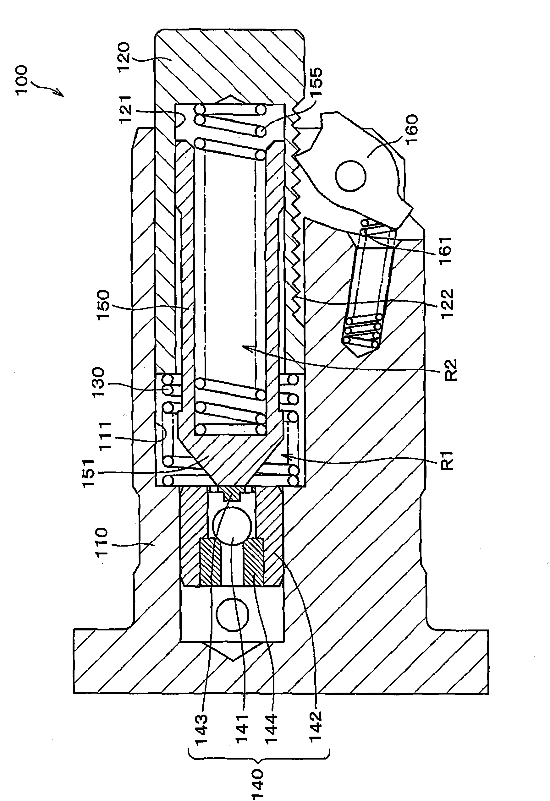
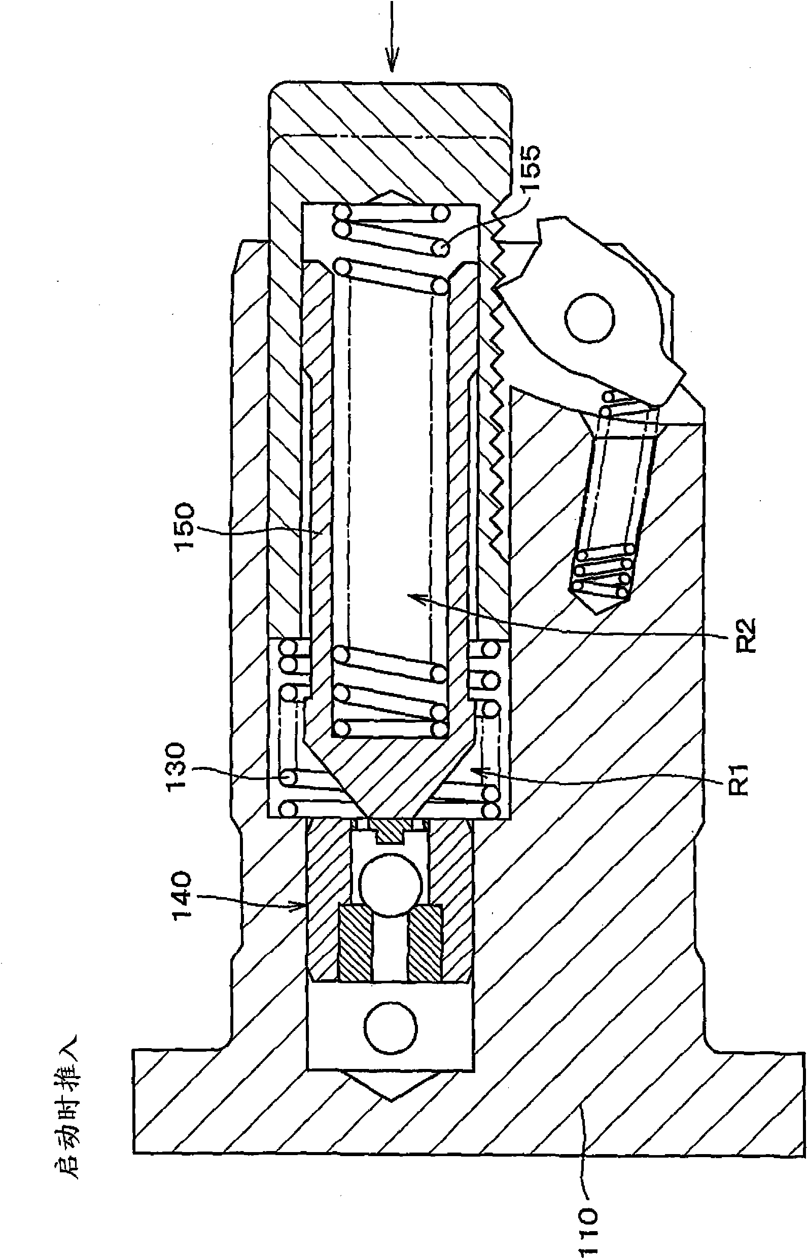
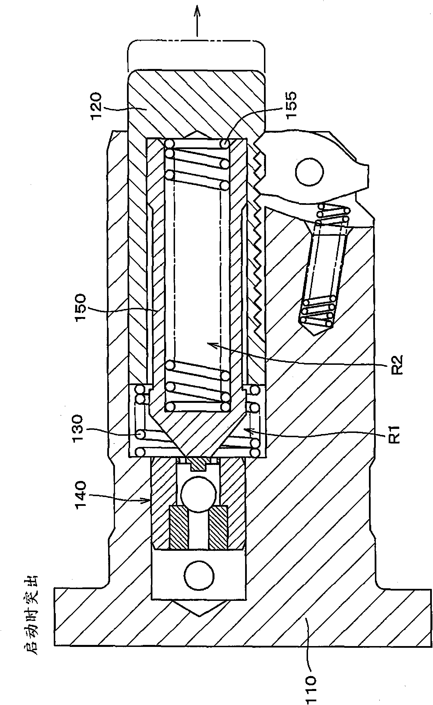
[0050] The hydraulic tensioner of the present invention comprises: a housing main body, a push rod receiving hole provided on the housing main body, a push rod protruding freely slidably from the push rod receiving hole, The high-pressure oil chamber formed between the push rods, the push rod urging spring that is accommodated in the high-pressure oil chamber and urges the push rod in the direction to protrude, is installed in the bottom of the above-mentioned push rod housing hole to stop the high-pressure oil. In the check valve unit for the reverse flow of pressure oil in the chamber, the push rod has an inner sleeve receiving hole on the side of the above-mentioned high-pressure oil chamber, and the inner sleeve receiving hole is slidably accommodated in the above-mentioned high-pressure oil chamber. The inner sleeve, the inner sleeve is biased in the direction of the check valve unit by the inner sleeve urging spring provided at the bottom of the inner sleeve receiving hol...


PUM


Abstract

The invention provides a hydraulic tension device which can prevent the vibration and noise during engine starting and maintain a proper racking pressure of the push bar in the common operation even after the pressure oil is filled. In the hydraulic tension device buffered by oil and forcing the push bar by a spring in the high pressure oil section, the high pressure oil section is divided into two inner sleeves slidably accommodated in an accommodating hole of the inner sleeve on the push bar and the high pressure oil section is forced to the direction of a check valve unit by the spring forced by the inner sleeve.

Description

technical field [0001] The present invention relates to a hydraulic tensioner for applying appropriate tension to, for example, a timing belt of a vehicle engine, a timing chain, and the like. Background technique [0002] A hydraulic tensioner with a one-way valve mechanism is widely used on timing belts or timing chains that transmit rotation between the crankshaft and camshaft of an engine for a vehicle to suppress vibration generated during their operation and maintain proper tension. [0003] Such an existing hydraulic tensioner 500 with a one-way valve mechanism, such as Figure 7 As shown, the slack side of the timing chain C stretched between the driving side sprocket S1 rotated by the crankshaft of the engine and the driven side sprockets S2, S2 fixed on the camshaft is attached to the engine main body, and the push rod 520 The push rod 520 protrudes freely from the front of the housing main body 510, and the push rod 520 pushes the back surface near the swing end ...

Claims


Application Information

Patent Timeline
Patent Type & Authority Applications(China)
IPC IPC(8): F16H7/08F01L1/348
CPCF16H2007/0859F16H7/0836F16H7/0848F16H2007/0853F16H2007/0812F16H2007/0806F16H7/18F16H7/08
Inventor 榑松勇二
Owner TSUBAKIMOTO CHAIN CO
Why Eureka
Try Eureka