

Elevator device
A technology of elevators and car boxes, which is applied to elevators, transportation and packaging, elevators, etc. in buildings, and can solve problems such as impact, poor control, and small effects
- Summary
- Abstract
- Description
- Claims
- Application Information
AI Technical Summary
Problems solved by technology
Method used
Image

Examples
Embodiment approach 1
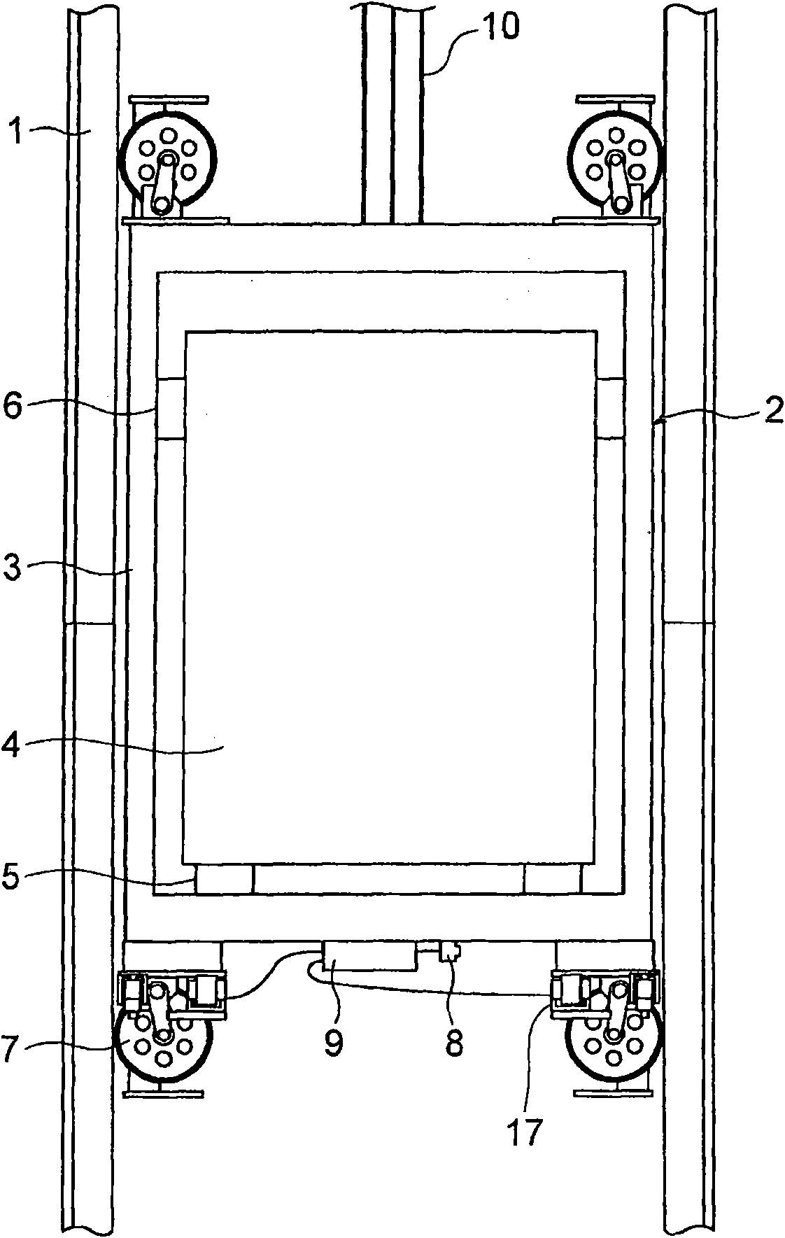
[0024] figure 1 It is a front view showing main parts of the elevator apparatus according to Embodiment 1 of the present invention. In the figure, a pair of guide rails 1 are provided in the lifting path. The car 2 is guided on the guide rail 1 to be raised and lowered in the raising and lowering path. In addition, the car 2 has a car frame 3 and a car room 4 supported inside the car frame 3 . Between the car chamber 4 and the lower beam of the car frame 3, a plurality of anti-vibration rubbers 5 are inserted as anti-vibration bodies (elastic bodies). In addition, between the side surfaces of the car room 4 and the left and right vertical columns of the car frame 3, a plurality of vibration-damping rubbers 6 are inserted as vibration-proof bodies (elastic bodies) for preventing the car room 4 from collapsing.
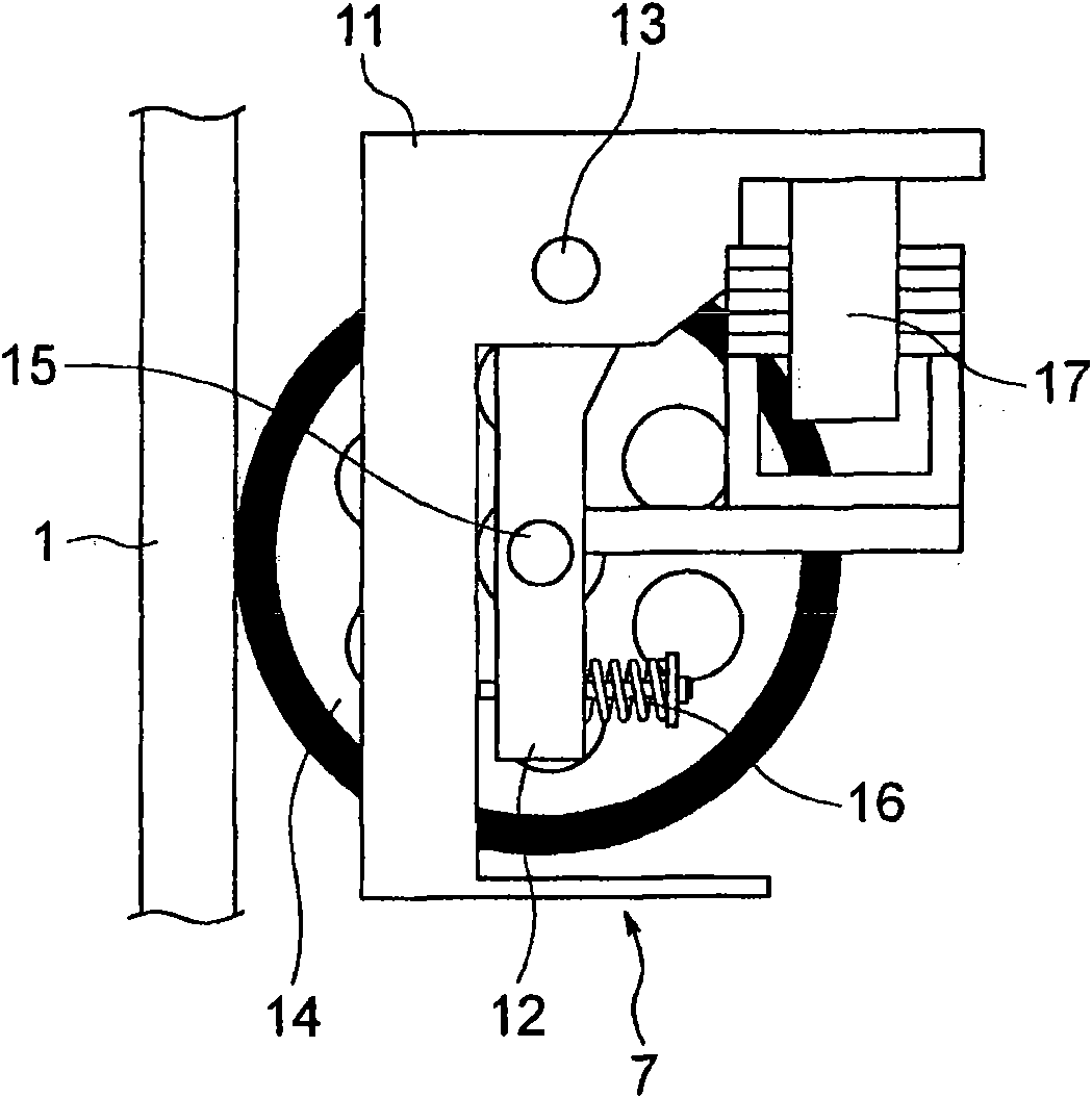
[0025] Roller guide devices 7 that engage with guide rails 1 to guide the lift of the car 2 are respectively mounted on both ends in the width direction of the upper...
Embodiment approach 2
[0052] Next, Embodiment 2 of the present invention will be described. In Embodiment 2, a voice coil actuator is used as the actuator 17 . Figure 6 It is an explanatory diagram showing the principle of a voice coil actuator. In the figure, the coil 33 is located in a magnetic circuit indicated by an arrow 34 . When a current is passed through the coil 33 as indicated by the arrow 35, by Fleming's left-hand rule, from Figure 6 The inner side of the paper facing the surface generates a Lorentz force proportional to the strength of the magnetic field and the value of the current. An actuator utilizing this Lorentz force is a voice coil actuator.
[0053] On the other hand, when the coil 33 moves in the magnetic field, counter electromotive force occurs in the coil 33 . For example, at coil 33 from Figure 6 When the surface of the paper of 1 moves toward the back side, a counter electromotive force that causes a current to flow in the direction opposite to the arrow 35 is g...
Embodiment approach 3
[0059] Next, Figure 8 It is a front view showing main parts of the elevator apparatus according to Embodiment 3 of the present invention. In the figure, between the lower beam of the car frame 3 and the lower part of the car room 4, an actuator 37 for generating a damping force for reducing lateral vibration generated in the car room 4 is provided. The acceleration sensor 8 and the vibration damping control unit 9 are installed in the car compartment 4 . In addition, the actuator 17 is not provided in the roller guide rail device 7 . Other structures are the same as those in Embodiment 1.
[0060] Figure 9 is shown by Figure 8 The curve of the open-loop gain characteristic of the feedback loop constituted by the actuator 37, the acceleration sensor 8, and the vibration damping control unit 9. When Kp is the gain value of the multiplier 23 and s is the Laplacian operator, the characteristic in the frequency domain lower than the first-order natural frequency wp1 is repr...
PUM
 Abstract
Description
Claims
Application Information