Glass ribbon producing apparatus and process for producing the same

The technology of a manufacturing device and manufacturing method, which is applied in the manufacturing device of glass ribbon and its manufacturing field, can solve the problems of uneven thickness of glass ribbon, accelerated glass ribbon flow down speed, difficulty of glass ribbon, etc.

Inactive Publication Date: 2012-06-13
NIPPON ELECTRIC GLASS CO LTD
View PDF6 Cites 2 Cited by
  • Summary
  • Abstract
  • Description
  • Claims
  • Application Information

AI Technical Summary

Problems solved by technology

Therefore, once the glass ribbon is cooled (hardened) to a certain extent, the thickness of the glass ribbon cannot be reduced thereafter. Therefore, even if the flow rate of the glass ribbon is increased, the thickness of the glass ribbon can be reduced. also limited
In particular, it is extremely difficult to form a glass ribbon with a plate thickness of 0.5 mm or less by this method
[0007] In addition, when the flow-down speed of the glass ribbon is increased too much, the flow-down speed of the unhardened glass ribbon whose shape is unstable is unduly increased, and therefore, the forming process of the glass ribbon is likely to be unstable, and the As a result, the thickness of the hardened glass ribbon tends to be uneven.
In addition, in order to increase the flow rate of the glass ribbon, it is necessary to clamp the glass ribbon and pull it downward strongly by a stretching mechanism such as rollers. Therefore, there is a risk of fatal problems such as surface scratches or cracks on the glass ribbon.

Method used


Image

  • Glass ribbon producing apparatus and process for producing the same
  • Glass ribbon producing apparatus and process for producing the same
  • Glass ribbon producing apparatus and process for producing the same

Examples


Embodiment Construction

[0061] Hereinafter, embodiments of the present invention will be described with reference to the drawings.

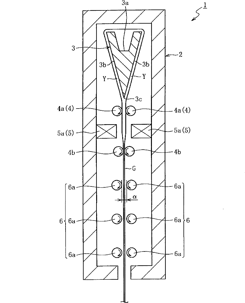
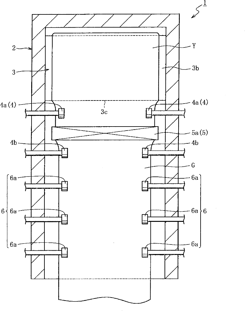
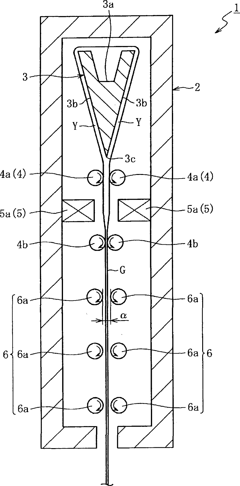
[0062] figure 1 It is a schematic longitudinal sectional side view schematically showing the internal state of a glass ribbon manufacturing apparatus according to an embodiment of the present invention, figure 2 It is a schematic longitudinal sectional front view schematically showing the internal state of the manufacturing apparatus. As shown in the above-mentioned figures, the manufacturing apparatus 1 includes a molded body 3 , a restricting mechanism 4 , a reheating mechanism 5 , and a guiding mechanism 6 sequentially from above inside a furnace 2 made of clay bricks.

[0063] The cross-sectional shape of the molded body 3 is wedge-shaped and has an overflow groove 3a at the top. The lower end part 3c of the molded object 3 fuses and becomes a plate form, and the molten glass Y which became this form is made to flow down as a plate-shaped glass ribbon G in an up-...


PUM

PropertyMeasurementUnit
thicknessaaaaaaaaaa

Abstract

The invention provides a glass ribbon producing apparatus (1) adapted to feed molten glass (Y) to molding member (2) and to cause the molten glass (Y) to flow downward from the molding member (2) so as to form sheetlike glass ribbon (G), comprising reheating means (5) disposed on a transport route for the glass ribbon (G) flowing downward from the molding member (2) so that the glass ribbon (G) is reheated by the reheating means (5) to thereby cause the sheet thickness of the glass ribbon (G) positioned inferior to the reheating means (5) to be smaller than that of the glass ribbon (G) positioned superior to the same.

Description

technical field [0001] This invention relates to the manufacturing apparatus of a glass ribbon, and its manufacturing method. Specifically, It is related with the improvement of the manufacturing technique of the glass ribbon by the so-called down-draw method which flows down molten glass from a molding body, and shapes a glass ribbon. Background technique [0002] As is well known, when producing sheet glass, there is a so-called down-draw method in which molten glass is flowed down from a molded body to form a glass ribbon as a raw sheet of sheet glass, and the representative methods include the overflow down-draw method (melting method), Orifice pull-down method. The former overflow down-draw method is to make the molten glass continuously supplied to the molded body having a wedge-shaped cross-sectional shape flow down from the top of the molded body along both sides, and fuse into a sheet-like form at the lower end of the molded body. A method in which a plate-shaped g...

Claims


Application Information

Patent Timeline
Patent Type & Authority Patents(China)
IPC IPC(8): C03B17/06
CPCC03B17/064C03B17/067C03B17/06
Inventor 笘本雅博织田英孝
Owner NIPPON ELECTRIC GLASS CO LTD
Why Eureka
Try Eureka