Vehicle lamp

A technology for vehicles and lamps, which is applied in the direction of headlights, road vehicles, vehicle parts, etc., can solve the problem of large coma aberration of the projection lens, and achieve the effect of suppressing shrinkage cavity

Active Publication Date: 2017-01-11
KOITO MFG CO LTD
View PDF8 Cites 0 Cited by
  • Summary
  • Abstract
  • Description
  • Claims
  • Application Information

AI Technical Summary

Problems solved by technology

[0006] In conventional projection-type vehicle lamps, as the projection lens, a plano-convex aspheric lens whose front surface is made

Method used


Image

  • Vehicle lamp
  • Vehicle lamp
  • Vehicle lamp

Examples


Embodiment Construction

[0073] Hereinafter, embodiments of the present invention will be described with reference to the drawings.

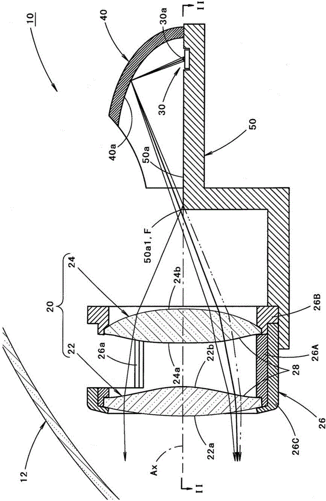
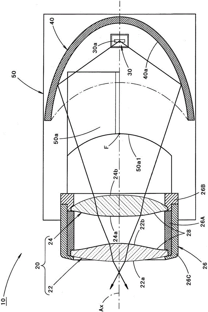
[0074] figure 1 It is a side sectional view showing a vehicle lamp according to an embodiment of the present invention. in addition, figure 2 Yes figure 1 sectional view of line II-II.

[0075] As shown in these figures, the vehicle lamp 10 according to the present embodiment is a headlamp for low beam installed at the front end of the vehicle, and is configured as a projection type lamp unit which is assembled in a lamp chamber, The lamp chamber is formed of a lamp body (not shown) and a transparent light-transmitting cover 12 attached to the front end opening of the lamp body.

[0076] That is, the vehicle lamp 10 has a structure including a projection lens 20 having an optical axis Ax extending in the vehicle front-rear direction, a light-emitting element 30, a reflector 40, and a base member 50, the light-emitting element 30 serving as a light source, The refl...


PUM


Abstract

In the case of a projection type vehicle lamp, even when the projection lens is composed of a plurality of lenses, it is possible to form a light distribution pattern having a high uniformity. The projection lens (20) is composed of two lenses (22, 24) arranged on an optical axis (Ax) extending in the front-rear direction of the vehicle. In this case, the rear main surface (Pr) of the projection lens (20) is formed by a convex curved surface having a large curvature as compared with a spherical surface (S1) having a rear focal point (F) as its center. As a result, the coma aberration extending toward the inner side (the optical axis side) is generated on the imaging surface of the projection lens (20); as a result, in the light distribution pattern formed by the light emitted from the projection lens (20), blurring caused by the coma aberration can form blurring with a tail extending toward the outside of the light distribution pattern, thus improving the uniformity of the light distribution pattern.

Description

technical field [0001] The present invention relates to a projection type vehicle lamp. Background technique [0002] Conventionally, a projection-type vehicle lamp is known, which is configured to irradiate forward light from a light source arranged behind a projection lens via a projection lens. [0003] In "Patent Document 1", as a projection lens in the above-mentioned vehicle lamp, a projection lens composed of two lenses arranged on an optical axis extending in the vehicle front-rear direction is described. [0004] Patent Document 1: Japanese Patent Laid-Open No. 2014-26741 [0005] In a vehicle lamp such as a headlamp, it is desirable to form a light distribution pattern with as little light unevenness as possible as a light distribution pattern formed by the irradiated light thereof. [0006] In conventional projection-type vehicle lamps, a plano-convex aspheric lens whose front surface is formed of a convex curved surface is often used as the projection lens, but...

Claims


Application Information

Patent Timeline
IPC IPC(8): F21S8/10F21V5/04F21V5/00F21W101/02F21W101/10F21Y115/10F21W107/10
CPCF21S41/25F21V5/008F21V5/04F21W2102/00F21W2107/10F21S41/148F21S41/155F21S41/295F21S41/321F21S41/365F21S41/43F21Y2115/10F21Y2115/30G02B19/0028G02B19/0061
Inventor 八木隆之
Owner KOITO MFG CO LTD
Why Eureka
Try Eureka