Scroll compressor

A scroll compressor and scroll technology, which is used in rotary piston machinery, rotary piston pumps, mechanical equipment, etc., can solve the problems of reduced compressor efficiency, increased power consumption of the compressor, and seizure of the front end of the wall.

Active Publication Date: 2009-09-09
三电株式会社
View PDF1 Cites 5 Cited by
  • Summary
  • Abstract
  • Description
  • Claims
  • Application Information

AI Technical Summary

Problems solved by technology

[0005] However, in the conventional structure described above, due to the structure that emphasizes the sealing performance between the wall front end of the scroll body of the scroll and the bottom plate surface of the other scroll, when the internal temperature or pressure of the compressor rises, , sometimes a large compressive force acts on the central part of the scroll body (at the same time on the front face side of the scrol

Method used


Image

  • Scroll compressor
  • Scroll compressor
  • Scroll compressor

Examples


Embodiment Construction

[0039] Hereinafter, preferred embodiments of the present invention will be described with reference to the drawings.

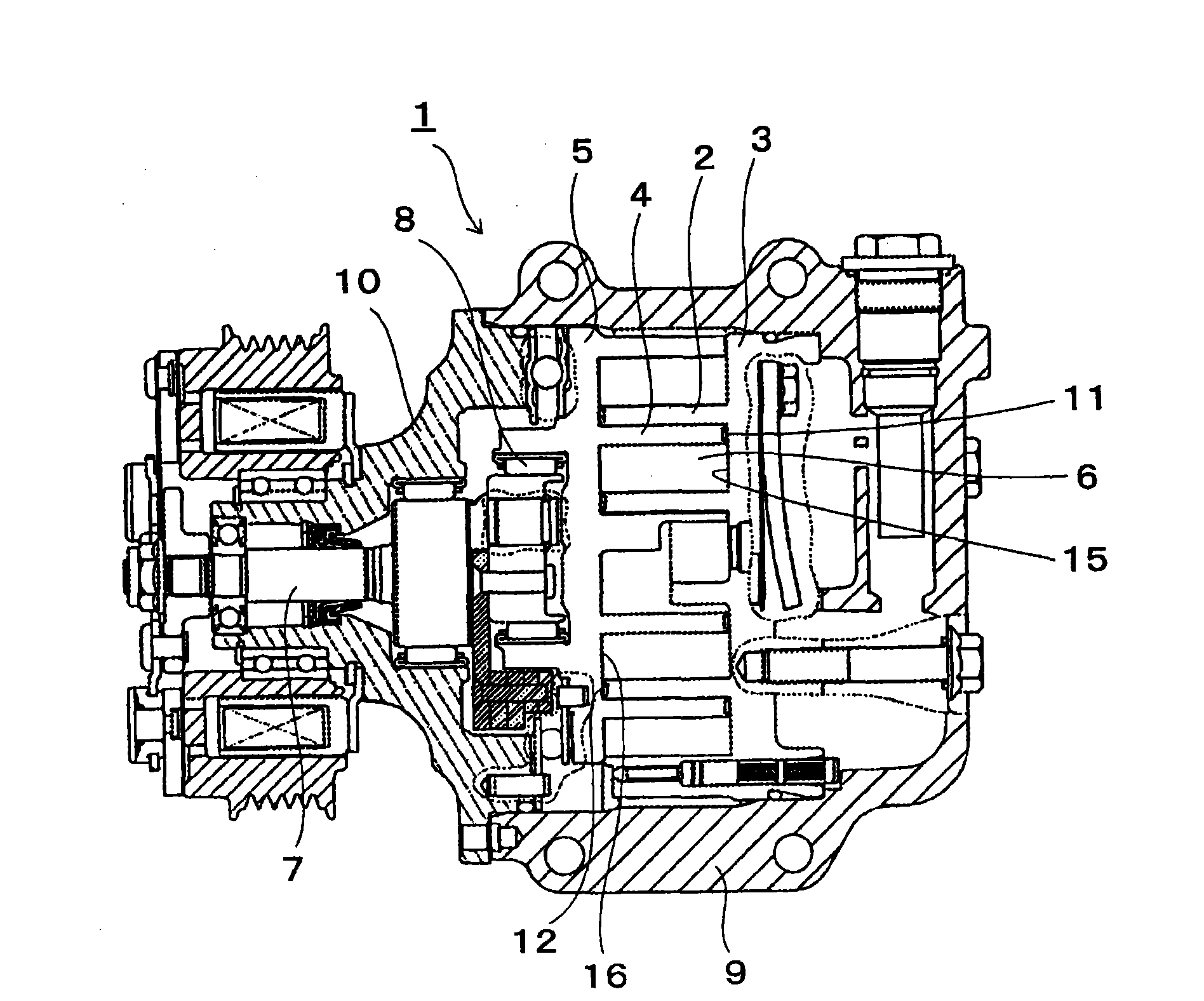
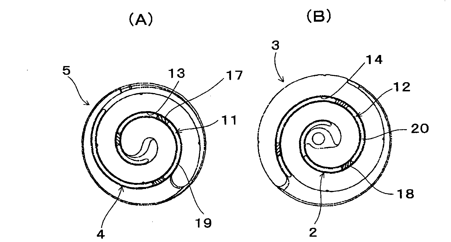
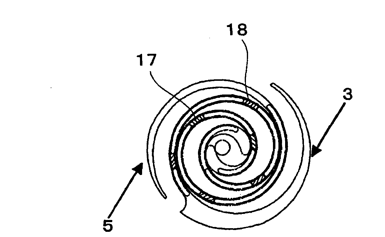
[0040] Figure 1 ~ Figure 3 A scroll compressor according to an embodiment of the present invention is shown. exist figure 1 Among them, symbol 1 represents the entire scroll compressor, which has a fixed scroll 3 and a movable scroll 5 meshing with each other, while the fixed scroll 3 includes a scroll body 2, and the movable scroll 5 includes a scroll body 4 . The movable scroll 5 orbits relative to the fixed scroll 3 while its rotation is blocked, and the fluid chamber 6 formed between the two scrolls moves toward the center to compress the fluid. The movable scroll 5 is driven by a drive shaft 7 constituted by a crankshaft, and a driving force for orbiting is transmitted to the movable scroll 5 through a drive bearing 8 press-fitted into the back side of the movable scroll 5 . figure 1 The symbol 9 in represents the main body shell, and the symbol 10...


PUM


Abstract

In a scroll compressor, a fixed scroll (3) and movable scroll (5) each having a spiral body are engaged with each other, grooves (13, 14) extending along the spiral shape of the spiral body are formed in the forward end surface of the spiral body of at least either one of the fixed scroll and movable scroll, and tip seals (11, 12) are disposed in the grooves so as to project from the forward end surface and be slidable on the bottom plate surface of the other scroll facing the forward end surface. The tip seals have large projection parts (17, 18) with a larger amount of projection from the forward end surface and also have small projectionparts (19, 20) with a smaller amount of projection from the forward end surface, and the large projection parts and small projection parts are arranged alternately in the direction along the spiral shape of the spiral body. The scroll compressor does not produce an excessive load at the end of the wall of the scroll while achieving the same sealability as in the case of conventional structures, i.e., the efficiency of the compressor can be improved.

Description

technical field [0001] The present invention relates to a scroll compressor used in a general air conditioner, a vehicle air conditioner, etc., and particularly relates to the structure of a blade end seal installed at the front end of a scroll wall. Background technique [0002] There is known a scroll compressor in which a fixed scroll and a movable scroll with a scroll mesh with each other, and the movable scroll orbits relative to the fixed scroll so that a space is formed between the scrolls of the two scrolls. The volume of the fluid chamber decreases while moving toward the center side, thereby compressing the fluid (for example, refrigerant) in the fluid chamber. In such a scroll compressor, in order to seal the inside of the fluid chamber, the following structure is generally adopted: a groove extending along the scroll shape of the scroll body is formed on the front end surface of the scroll body of the scroll, and A tip seal is arranged in the groove, and the tip...

Claims


Application Information

Patent Timeline
IPC IPC(8): F04C18/02
CPCF01C19/005F04C18/0215F04C18/0246F04C27/005
Inventor 工藤孝行
Owner 三电株式会社
Why Eureka
Try Eureka