Rotation damper

A technology of rotating shock absorbers and rotors, which is applied in liquid shock absorbers and other directions, can solve the problems of uneven torque and unstable torque, and achieve the goal of reducing uneven torque and reducing torque Unevenness, the effect of preventing abnormal noise

Inactive Publication Date: 2009-09-09
NIFCO INC
View PDF1 Cites 3 Cited by
  • Summary
  • Abstract
  • Description
  • Claims
  • Application Information

AI Technical Summary

Problems solved by technology

[0008] In addition, if the air position in the housing is not determined, stable torque cannot be obtained, and unevenness in torque occurs.

Method used


Image

  • Rotation damper
  • Rotation damper
  • Rotation damper

Examples


Embodiment Construction

[0059] Hereinafter, embodiments of the present invention will be described with reference to the drawings.

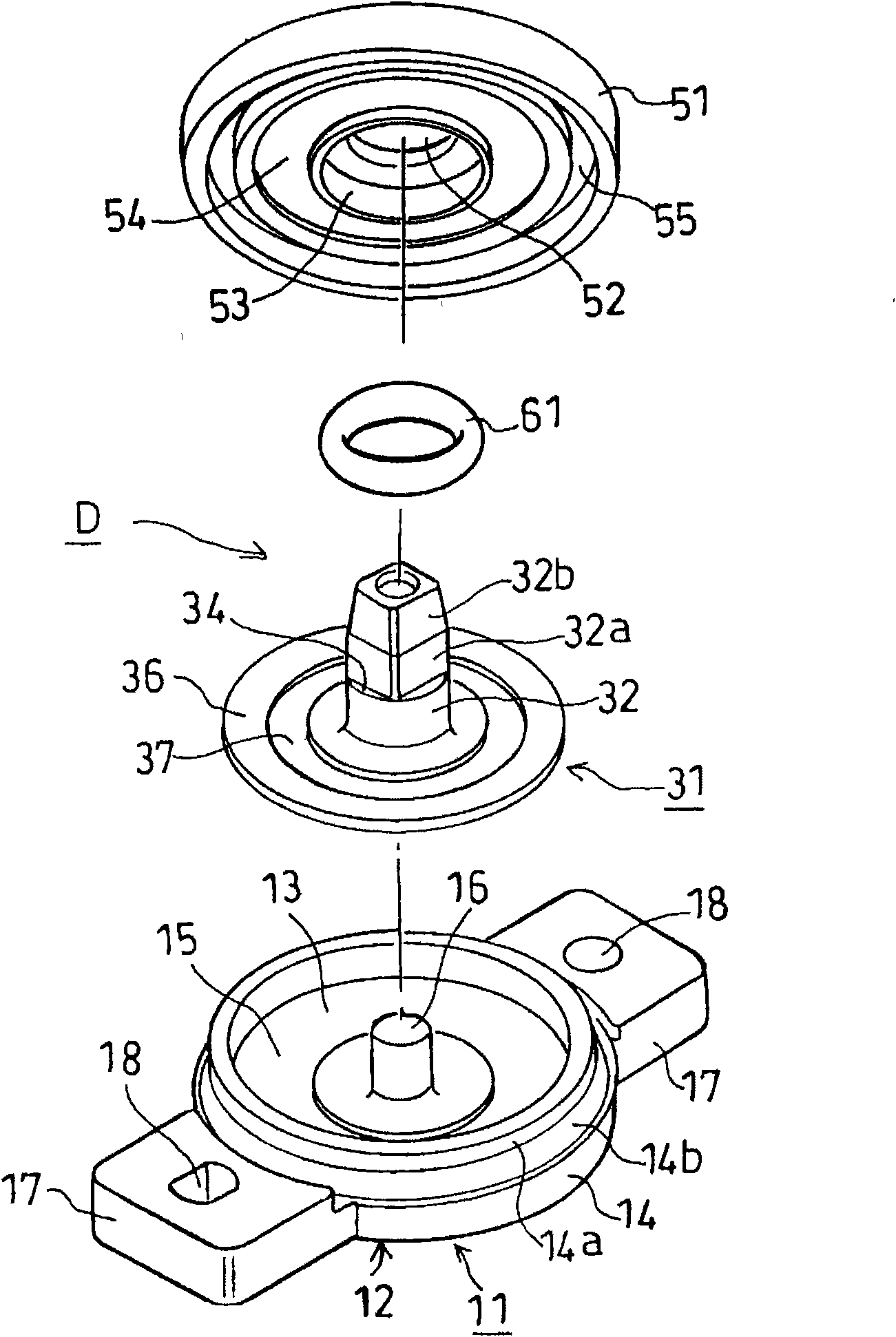
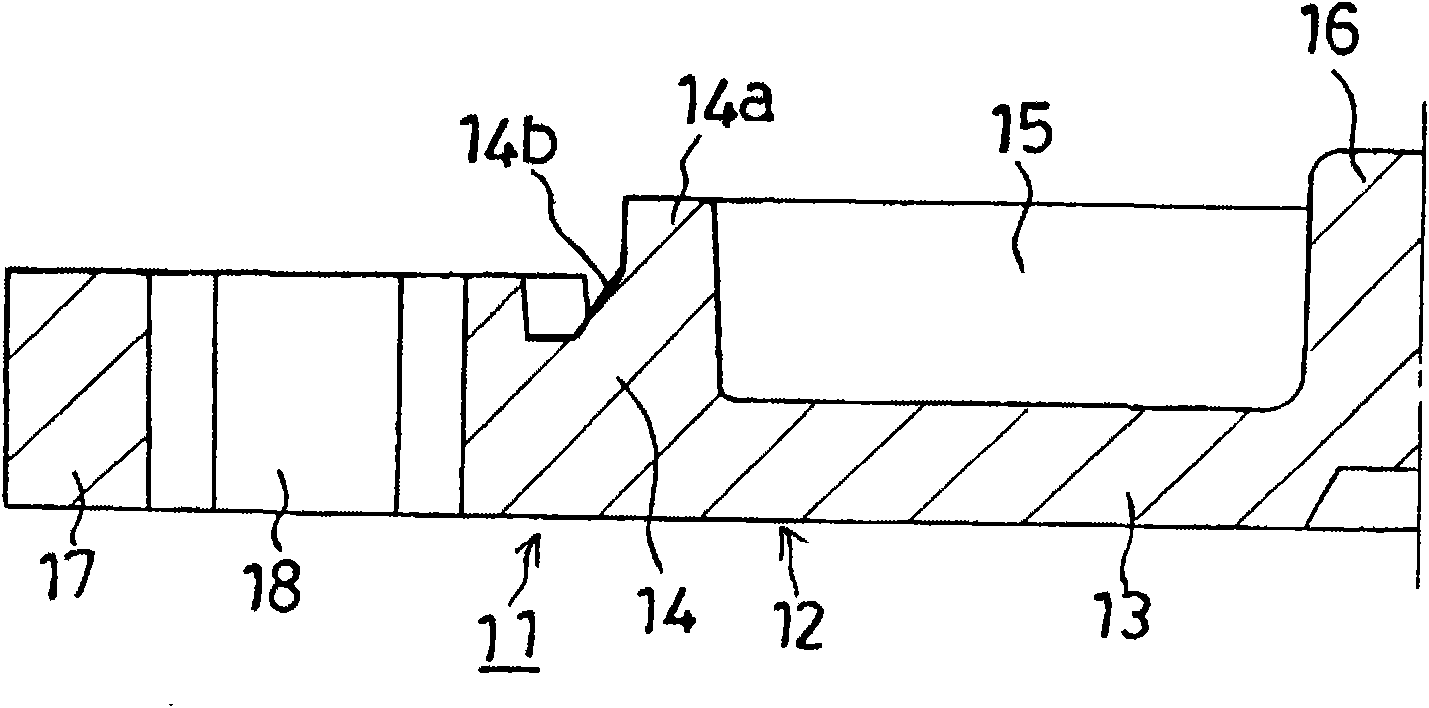
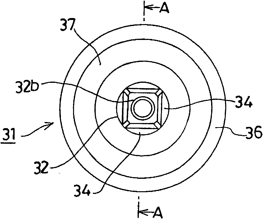
[0060] figure 1 It is an exploded perspective view showing the rotation damper of the first embodiment of the present invention, figure 2 yes figure 1 An enlarged cross-sectional view of the left half of the housing is shown, image 3 yes figure 1 A top view of the rotor shown, Figure 4 yes figure 1 Front view of the rotor shown, Figure 5 yes figure 1 Bottom view of the rotor shown, Figure 6 is along image 3 A sectional view of the A-A line, Figure 7 yes figure 1 An enlarged cross-sectional view of the left half of the lid shown, Figure 8 is assembly figure 1 An explanatory diagram of the process of rotating the shock absorber shown, Figure 9 It is a sectional view showing the rotation damper according to the first embodiment of the present invention.

[0061] exist figure 1 Among them, D represents a rotary damper, including: a synthetic resin ca...


PUM


Abstract

A rotation damper adapted such that air mixed in housings during assembly is not excessively compressed to prevent production of noise by the air even if a rotator is rotated in both directions and that the air is collected and made to stay at a specific portion to reduce an influence of the air to generated torque, making variation in the torque as small as possible. The rotation damper (D) has housings (11, 51), silicone oil (21) received in the housings (11, 51), a rotor (31) received in the housings (11, 51) and having a resistance section (36) that is provided on a shaft (32) projecting from the housings (11, 51) and moves in the silicone oil (21) in the housings (11, 51), and an O-ring (61) for preventing the silicone oil (21) from leaking between the shaft (32) and the housing (51). A circumferential groove (54) is formed in the inner surface of the housing (51).

Description

technical field [0001] The present invention relates to, for example, a rotary damper that brakes the rotation of a driven gear that meshes with a gear or a rack. Background technique [0002] The above-mentioned rotary damper includes: a housing; a viscous fluid accommodated in the housing; and a rotor accommodated in the housing, and a resistance part that moves in the viscous fluid in the housing is provided on a shaft part protruding from the housing. ; A sealing member that prevents viscous fluid from leaking between the shaft portion of the rotor and the housing. [0003] Furthermore, a driven gear is attached to a shaft protruding from the housing (for example, JP-A-4-34015). [0004] In the conventional rotary damper, the shape of the resistance part is designed to be roughly elliptical in order to prevent the air mixed into the housing from entering between the resistance part of the torque generating part, that is, the rotor, and the bottom or top surface of the h...

Claims


Application Information

Patent Timeline
Patent Type & Authority Applications(China)
IPC IPC(8): F16F9/12
CPCF16F9/12F16F9/10
Inventor 山口惠二神保直人富田重光冈林俊辅北川绫子滕文欣平野裕树小泉一贵武井嘉久
Owner NIFCO INC
Why Eureka
Try Eureka