Shift control device for industrial vehicle

A technology for industrial vehicles and control devices, applied in the directions of adaptive control, transmission control, general control system, etc., can solve the problems of large driving force, inability to obtain sufficient driving force, etc., and achieve the effect of sufficient driving force

Active Publication Date: 2013-02-06
NIHON KENKI CO LTD
View PDF2 Cites 0 Cited by
  • Summary
  • Abstract
  • Description
  • Claims
  • Application Information

AI Technical Summary

Problems solved by technology

[0004] However, for example, when driving a wheel loader into accumulated sand and digging, a large driving force is required
However, in the device described in the above-mentioned Patent Document 1, since the gear up is automatically performed when the speed of the torque converter is relatively high, for example, even if it rushes into the sand and soil in the 1st speed state, it may happen that the gear is shifted just before the speed. When the gear is shifted to 2nd speed, it may not be possible to obtain sufficient driving force during excavation work.

Method used


Image

  • Shift control device for industrial vehicle
  • Shift control device for industrial vehicle
  • Shift control device for industrial vehicle

Examples


Embodiment Construction

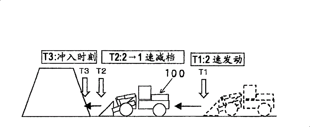
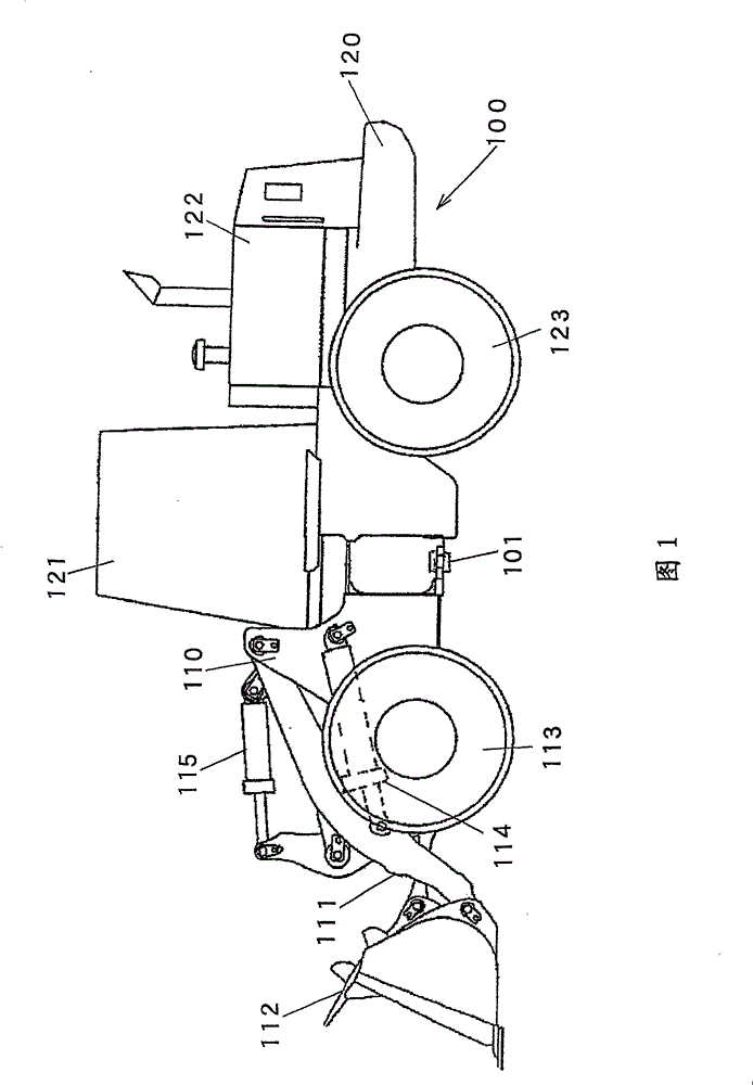
[0022] Below, refer to Figure 1 to Figure 8 A transmission control device for an industrial vehicle according to an embodiment of the present invention will be described.

[0023] figure 1 It is a side view of a wheel loader, which is an example of an industrial vehicle to which the speed change control device of this embodiment is applied. The wheel loader 100 is composed of a front body 110 having an arm 111 , a bucket 112 , tires 113 and the like, and a rear body 120 having a cab 121 , an engine compartment 122 , tires 123 and the like. The arm 111 is rotated vertically (pitch motion) by the drive of the arm cylinder 114 , and the bucket 112 is rotated vertically by the drive of the bucket hydraulic cylinder 115 (unloading or loading). Front body 110 and rear body 120 are rotatably connected to each other by center pin 101 , and front body 110 is bent left and right relative to rear body 120 by expansion and contraction of a steering cylinder (not shown).

[0024] fig...


PUM


Abstract

A gearshift controller for an industrial vehicle, includes: a speed ratio detection unit that detects a speed ratio of speeds of an input axis and of an output axis of a torque converter; a gearshift control unit that shifts up a speed stage when the detected speed ratio is equal to or more than a first predetermined value and shifts down the speed stage when the detected speed ratio is equal to or less than a second predetermined value, which is smaller than the first predetermined value; and an operation member with which a downshift to the first speed is instructed by operation thereof by an operator. When the downshift is instructed by the operationmember, the gearshift control unit controls the speed stage to be kept at the first speed for a predetermined time period regardless of the speed ratio detected by the speed ratio detection unit.

Description

technical field [0001] The present invention relates to a speed change control device for industrial vehicles such as wheel loaders. Background technique [0002] Conventionally, there is known a device that transmits an output torque of an engine to a transmission via a torque converter (hereinafter referred to as a torque converter) (for example, refer to Patent Document 1). In the device described in this patent document 1, the ratio of the speed ratio between the input shaft side and the output shaft side of the hydraulic torque converter is calculated, and when the speed ratio reaches a predetermined value, it is automatically shifted up or down. files. [0003] Patent Document 1: Japanese Patent No. 3388594 [0004] However, a large driving force is required, for example, to perform excavation work by dashing a wheel loader into accumulated sand and soil. However, in the device described in the above-mentioned Patent Document 1, since the gear up is automatically pe...

Claims


Application Information

Patent Timeline
Patent Type & Authority Patents(China)
IPC IPC(8): F16H61/18F16H59/12E02F9/20
CPCE02F9/2025E02F9/2004F16H61/16G05B13/02F16H2059/467E02F9/2079E02F9/16E02F9/2253F16H61/18F16H59/12E02F9/20
Inventor 兵藤幸次田中哲二酒井荣一石丸源一郎高桥智雄山崎恭央
Owner NIHON KENKI CO LTD
Why Eureka
Try Eureka