Gas supply device for wafer container

A wafer container and gas supply technology, which is applied in the direction of electrical components, semiconductor/solid-state device manufacturing, circuits, etc., can solve the problems of wasting purge gas, purge gas leakage, and reducing the productivity of wafer processing processes, so as to prevent waste and improve productivity effect

Active Publication Date: 2022-03-08
JUSTEM CO LTD
View PDF6 Cites 0 Cited by
  • Summary
  • Abstract
  • Description
  • Claims
  • Application Information

AI Technical Summary

Problems solved by technology

[0014] However, the upward driving force provided by the spring or the hydraulic or pneumatic cylinder is limited, and even if the wafer container is separated due to the additional load generated at the initial stage of driving, the nozzle cannot be fully lifted because the upward driving force is not provided sufficiently. high
[0015] If the nozzle cannot be raised sufficiently, the purge gas is continuously supplied even in the state where the wafer container is not installed, thereby wasting the purge gas; since the gas supply device is not driven smoothly, the productivity of the wafer processing process is reduced; Installing the wafer container in a raised state lowers the airtightness between the wafer container and the nozzle, so there is a problem of purge gas leakage

Method used


Image

  • Gas supply device for wafer container
  • Gas supply device for wafer container
  • Gas supply device for wafer container

Examples


Embodiment Construction

[0070] Hereinafter, embodiments of the present invention will be described in detail with reference to the drawings.

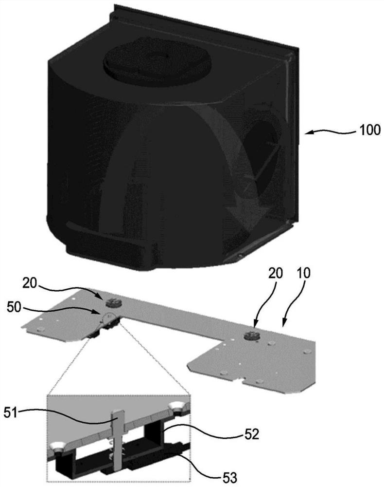
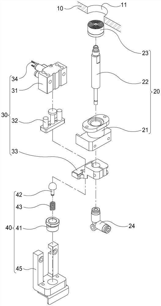
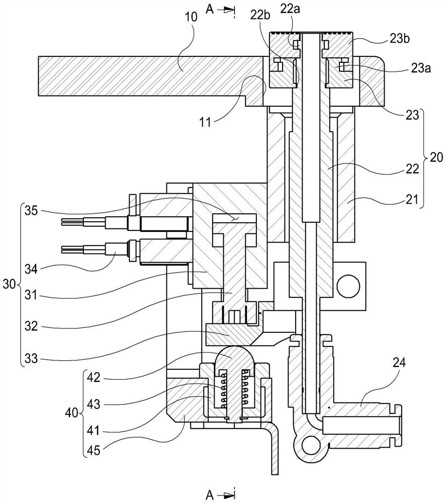
[0071] figure 1 is a block diagram showing a gas supply device for a wafer container according to the first embodiment of the present invention; figure 2 is an exploded view showing the gas supply device of the wafer container of the first embodiment of the present invention; image 3 is a front sectional view showing a state in which a nozzle of the gas supply device for a wafer container according to the first embodiment of the present invention is raised; Figure 4 yes image 3 Sectional view of "A"; Figure 5 is a front sectional view showing a state in which a nozzle of the gas supply device for a wafer container according to the first embodiment of the present invention is lowered; Image 6 yes Figure 5 Sectional view of "B"; Figure 7 is an exploded view showing a gas supply device for a wafer container of a second embodiment of the present inve...


PUM


Abstract

The present invention relates to a gas supply device for a wafer container that injects purge gas into a wafer container that accommodates and transports wafers. The gas supply device for the wafer container includes: a stage portion on which the wafer container is installed; a gas inlet and outlet portion corresponding to the positions of the gas inlet and the gas outlet formed in the wafer container, and includes a casing and a nozzle, wherein the casing is combined with the stage part, the nozzle is lifted and inserted into the housing, and a flow path for purge gas to enter and exit is formed inside; the first drive part is connected to the nozzle to lift up and down, and provides an upward driving force to make the nozzle Rising: the second driving part elastically supports the first driving part, and then provides elastic force in the direction in which the first driving part rises. Accordingly, the first and second driving units provide sufficient driving force to raise the nozzle, and when the wafer container is removed from the upper part of the nozzle, the nozzle can be raised smoothly, thereby preventing waste of purge gas.

Description

technical field [0001] The present invention relates to a gas supply device for a wafer container, and more specifically, to a gas supply device for a wafer container for injecting a purge gas into a wafer container for accommodating and transporting wafers. Background technique [0002] In general, semiconductor elements are manufactured through various wafer processes, including the following processes: a deposition process for forming a film on a wafer; a chemical / mechanical polishing process for planarizing the film; A photolithography process for forming a photoresist pattern on the film; an etching process for patterning the film with electrical properties using the photoresist pattern; an ion implantation process for implanting specific ions in a fixed area of ​​the wafer ; a cleaning process for removing impurities on the wafer; an inspection process for inspecting the surface of the wafer on which the film or pattern is formed, etc. In addition, the heat treatment ...

Claims


Application Information

Patent Timeline
Patent Type & Authority Patents(China)
IPC IPC(8): H01L21/67H01L21/02H01L21/673
CPCH01L21/02041H01L21/02082H01L21/67017H01L21/6735H01L21/67389
Inventor 金弘烈
Owner JUSTEM CO LTD
Why Eureka
Try Eureka