Dehumidifier

A dehumidifier and rotor technology, applied in the field of dehumidifiers, can solve the problems of dehumidification capacity reduction, temperature rise, ventilation area narrowing, etc., and achieve the effect of expanding the area and reducing the resistance of the air path

Active Publication Date: 2009-09-16
MITSUBISHI ELECTRIC CORP +1
View PDF1 Cites 4 Cited by
  • Summary
  • Abstract
  • Description
  • Claims
  • Application Information

AI Technical Summary

Problems solved by technology

[0011] (3) In addition, if the distance between the dehumidification rotor and the partition plate and the gap between the dehumidification rotor and the heater unit are set to be large in order to avoid this contact, air leakage from the gap will increase.
In addition, in the dehumidification air path, the temperatu

Method used


Image

  • Dehumidifier
  • Dehumidifier
  • Dehumidifier

Examples


Embodiment approach 1

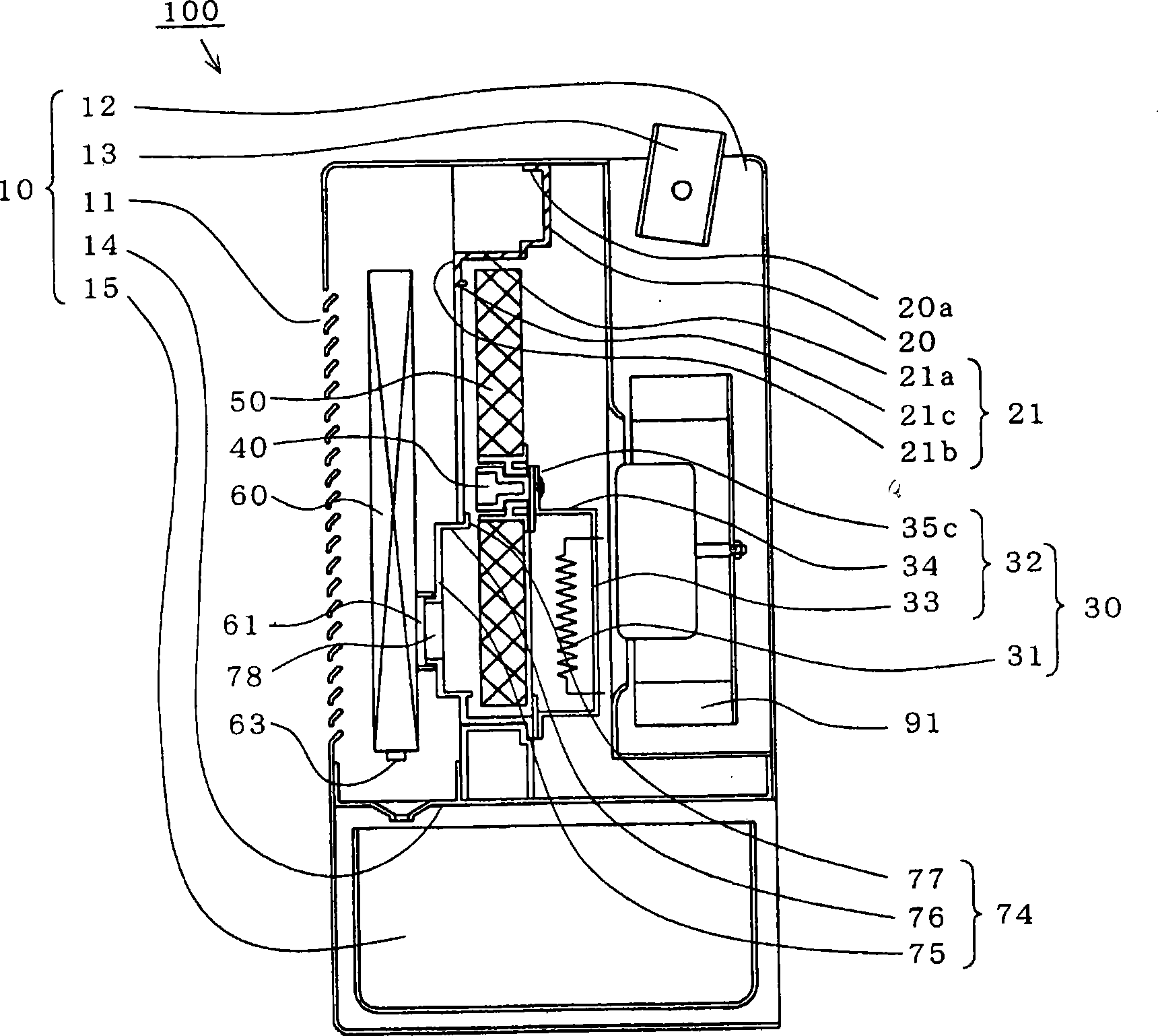
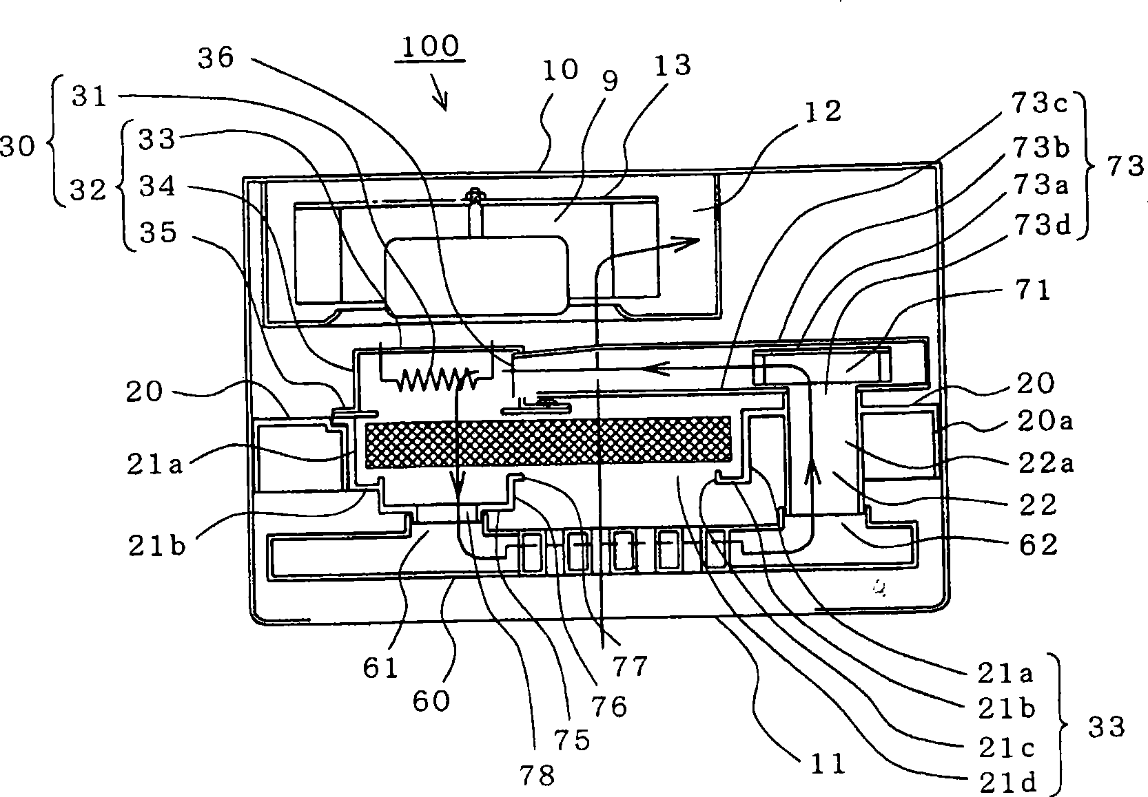
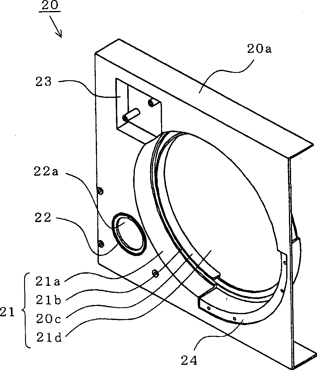
[0041] Figure 1 to Figure 9 is a diagram schematically showing a dehumidifier according to an embodiment of the present invention, figure 1 is a side sectional view, figure 2 is a top sectional view, image 3 is a perspective view showing a part (frame), Figure 4 (a) is a rear view showing a part (heater unit), Figure 4 (b) is a sectional view showing a rear view of one part (heater unit), Figure 5 It is an exploded perspective view showing the configuration of one part (regeneration air circulation member), Figure 6 It is a cross-sectional view showing one part (shaft support member), Figure 7 is a sectional view showing one part (rotor rotating member), Figure 8 It is a front view showing one part (air regeneration collector), Figure 9 (a) is a front view showing a part (regeneration air condenser), Figure 9 (b) is a front view showing the wind flow in one part (regeneration air condenser). In addition, in each figure, the same code|symbol is attached|subjec...


PUM


Abstract

The present invention provides a dehumidifier that provides actual support to a dehumidification rotor and restrains air indoor and leakage of heated air at minimum. In the invention, the dehumidifier 100 is provided with a frame 20 with a big opening 21, a heater unit 30 fixed on the frame 20, a axle suspension component 40 fixed on the heater unit 30 inside a main housing 10, and the all-around dehumidification rotor 50 set on the axle suspension component 40 that can rotate freely and cover the big opening 21, forms a dehumidification wind path and a renewable wind path through the dehumidification rotor 50. Part that passes through the dehumidification rotor is returned to renewable air circle wind path of the heater unit 30 that fixed on a renewable fan housing 73 that fixed on the frame 20. The renewable fan housing 73 and the heater unit 30 are connected.

Description

technical field [0001] The present invention relates to a dehumidifier, particularly a dehumidifier having a rotating dehumidifying member. Background technique [0002] A conventional dehumidifier has a main body case in which a suction port for sucking indoor air and an exhaust port for discharging dry air are respectively formed, and a partition plate that divides the interior into a suction port side and an exhaust port side. Then, a circular opening is formed on the partition plate, and the desiccant rotor is rotatably installed so as to cover the opening. Then, a dehumidification air path is formed from the suction port to the exhaust port through a part of the desiccant rotor, and a regeneration circulation air path is formed to circulate through a part of the desiccant rotor in order to regenerate (desorb) moisture adsorbed by the desiccant rotor. [0003] In addition, a substantially cross-shaped support arm is integrally provided at the circular opening of the par...

Claims


Application Information

Patent Timeline
IPC IPC(8): B01D53/26F24F3/14
CPCB01D53/263F24F3/1423
Inventor 石川俊夫久下洋介柴田英雄
Owner MITSUBISHI ELECTRIC CORP
Why Eureka
Try Eureka