Mould with alterable brake bead resistance

A drawbead and resistance technology, which is applied in the field of variable drawbead height molds and variable drawbead resistance molds, can solve the problems that the variable drawbead resistance cannot be changed, achieve large adjustments, reduce production costs, and improve The effect of product quality

Inactive Publication Date: 2009-09-16
重庆工学院
View PDF0 Cites 18 Cited by
  • Summary
  • Abstract
  • Description
  • Claims
  • Application Information

AI Technical Summary

Problems solved by technology

[0003] The present invention aims at the problem that the existing mold cannot change the variable drawbead...

Method used


Image

  • Mould with alterable brake bead resistance
  • Mould with alterable brake bead resistance

Examples


Embodiment Construction

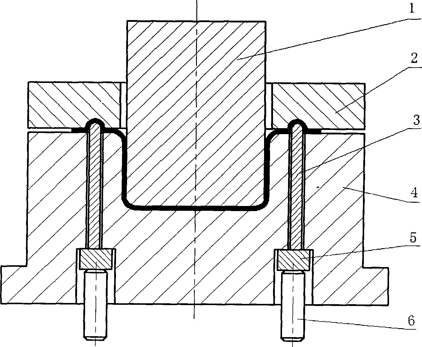
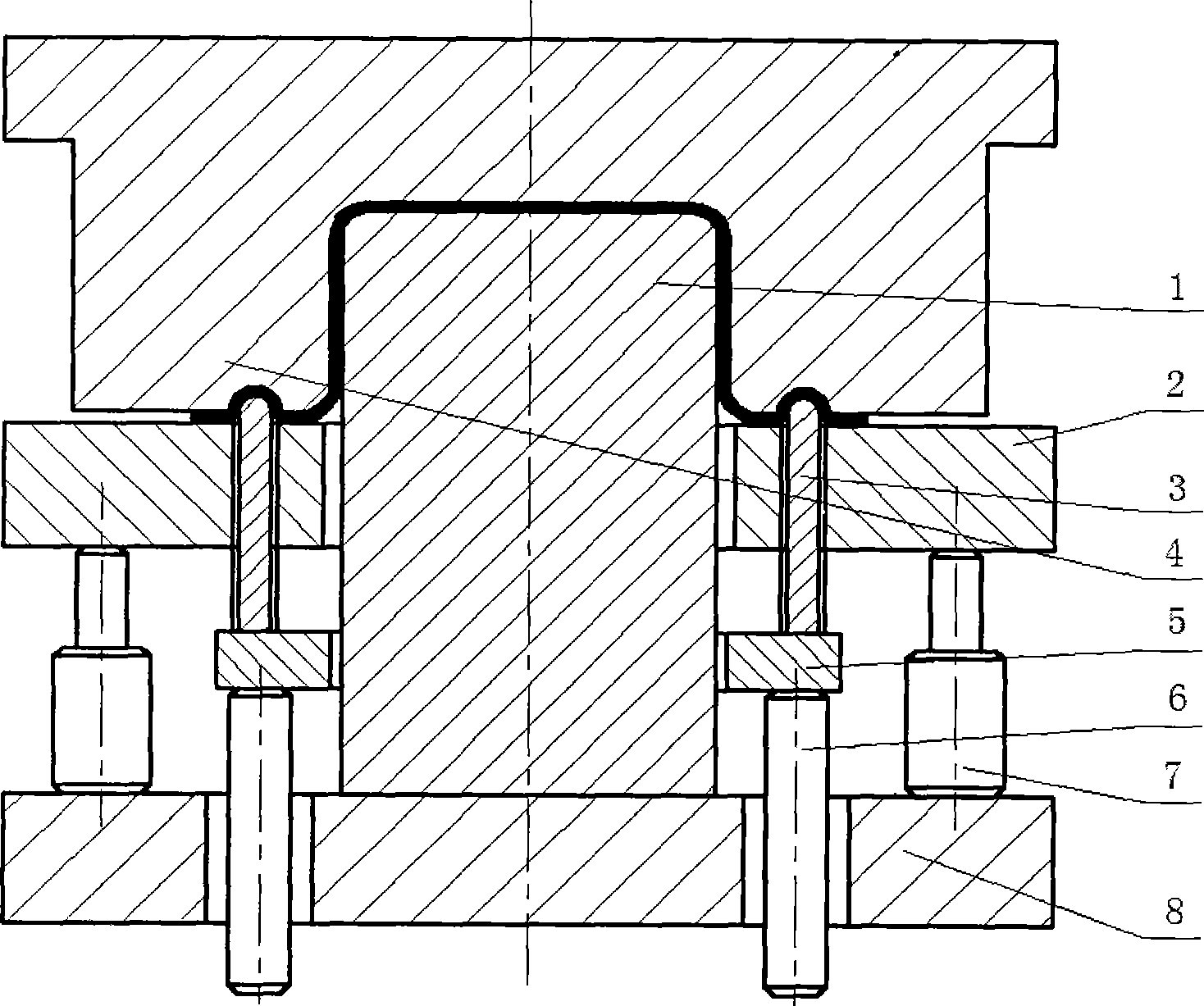
[0012] See figure 1 , Shown is the double-action press to change the drawbead resistance of the mold, including the punch 1, the die 4, the blank 2, the drawbead 3, the drawbead pad 5 and the ejector rod 6. The punch 1 is installed on the inner sliding block of the press, the pressing plate 2 is installed on the outer sliding block of the press, and the female mold 4 is installed on the worktable. At least one independent drawing bead 3 is also provided. The drawing bead 3 penetrates upward from the die 4, and the lower end is in contact with the upper end of the top rod 6 through the drawing bead pad 5. The ejector rod 6 pushes the drawbead pad 5 to move up and down, and the drawbead pad 5 pushes the drawbead 3 to move up and down synchronously to adjust the height of the drawbead 3 and adjust the height of the drawbead 3 to expose the die 4 (from The height of the die 4 penetrated upwards). The ejector rod 6 is connected with the air cushion, and the force provided by the eject...


PUM


Abstract

This invention discloses a mould with alterable brake bead resistance, comprising a punch, a matrix, a pressure plate, a brake bead, a brake bead bolster, an ejector rob and a nitrogen cylinder. The brake bead is separated from the matrix or the pressure plate, and the brake bead passes through the matrix or the pressure plate upwards, the lower end of the brake bead contact with the upper end of the ejector rob through the brake bead bolster. The ejector rob of the air cushion of the machine tool pushes the brake bead bolster and the brake bead bolster moves, the height of the brake bead is controlled by the air cushion through the ejector rob. In the entire drawing process, the brake bead resistance changes with the change of the stamping route. The brake bead resistance of this mould can be controlled easily and it is very useful to improve the quality of the product.

Description

Technical field [0001] The invention belongs to stamping die technology, and specifically relates to a variable drawbead resistance die, and is mainly aimed at a die with a variable drawbead height. technical background [0002] In current stamping dies, the convex ribs of the drawing bead are usually fixed on the blank or die, and the resistance of the drawing bead is constant throughout the drawing process. For the drawing forming that requires the resistance of the drawbead to be changed with the stamping stroke, this fixed form cannot be realized. At the same time, this method of fixing the drawbeads on the blank or die is not convenient for mold repair. Sometimes it may cause the blank or die to be scrapped because the drawbead can no longer be repaired, which increases the number of molds. The repairing time of the mold reduces the service life of the mold, thereby increasing the production cost. Summary of the invention [0003] Aiming at the problem that the existing mol...

Claims


Application Information

Patent Timeline
IPC IPC(8): B21D37/10
Inventor 李小平彭成允张侠唐丽文陈元芳吕琳胡建军
Owner 重庆工学院
Why Eureka
Try Eureka