Router table plate assembly

a router table and plate technology, applied in the field of router tables, can solve the problems of limited table size, router cannot be quickly removed for other jobs and reattached in the same location, and interfere with the use of the router table, so as to optimize the clamping geometry, and improve the effect of surface position adjustmen

Inactive Publication Date: 2008-08-12
LEE VALLEY TOOLS
View PDF17 Cites 12 Cited by
  • Summary
  • Abstract
  • Description
  • Claims
  • Application Information

AI Technical Summary

Benefits of technology

[0027]In order to accommodate the largest number of router bases, the slot that accepts the clamping post onto which the knurled nut is threaded permits the clamping arm to be positioned in a wide range of locations in order to optimize the clamping geometry. Additionally, the feet are two different lengths so that they terminate at different heights. This allows the clamps to be used in two different orientations to further optimize the clamping geometry.
[0028]Without structure preventing it, the slot might permit the clamp arms to slide along the clamping posts. This could conceivably permit the clamps to loosen unintentionally. To prevent this from occurring, the location of the arm relative to the clamping post is fixed when the clamps are engaged but adjustable when the clamps are released. This is accomplished by a series of grooves in the upper surface of the arm transverse to its length (and to the slot within which the post is received). These grooves receive one or more mating tabs on the underside of a washer on the clamping post under the knurled nut. When clamped together between the knurled nut and the router base, the washer tabs or protrusions engage one or two of the grooves and prevent the arm from sliding along the post.
[0029]In the plate levelers of this invention, an arm

Problems solved by technology

These holes can interfere with use of the router table.
Not all routers have such fence mounting holes.
Furthermore, because any clamping device would need to penetrate into the holes, the router cannot be quickly removed for other jobs and reattached in the same location.
In designs where the router is attached directly to the table, using screws or clamps, the size of the table is limited by the need to access the router either from below or by lifting the entire table.
In practice, the largest size that will enable needed access is less than that desirable for maximum safety and util

Method used


Image

  • Router table plate assembly
  • Router table plate assembly
  • Router table plate assembly

Examples


Embodiment Construction

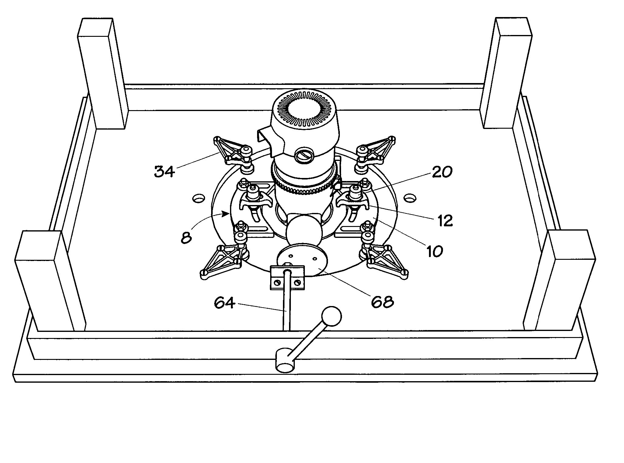
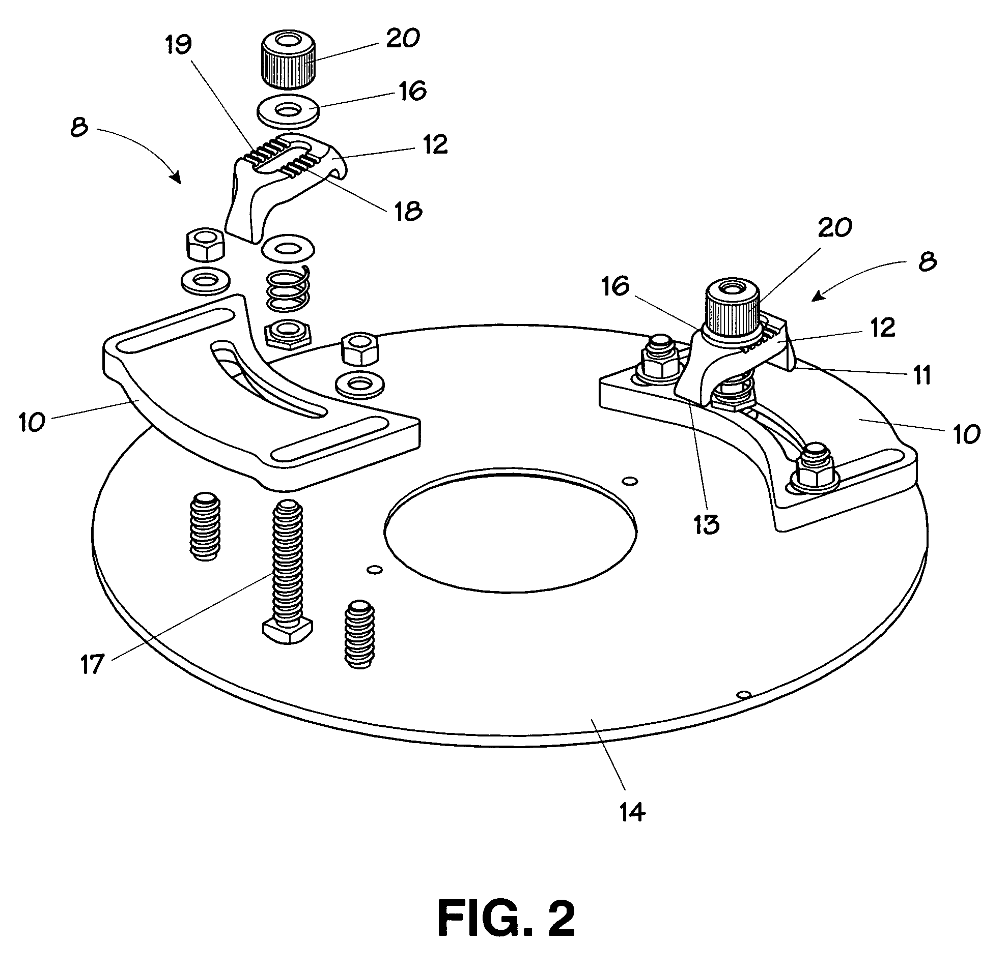
[0051]An illustrative embodiment of this invention is shown in FIG. 1 as a router table plate with router mounting clamps, a plate leveling system for securing and positioning the plate in the router table and a plate lift assembly.

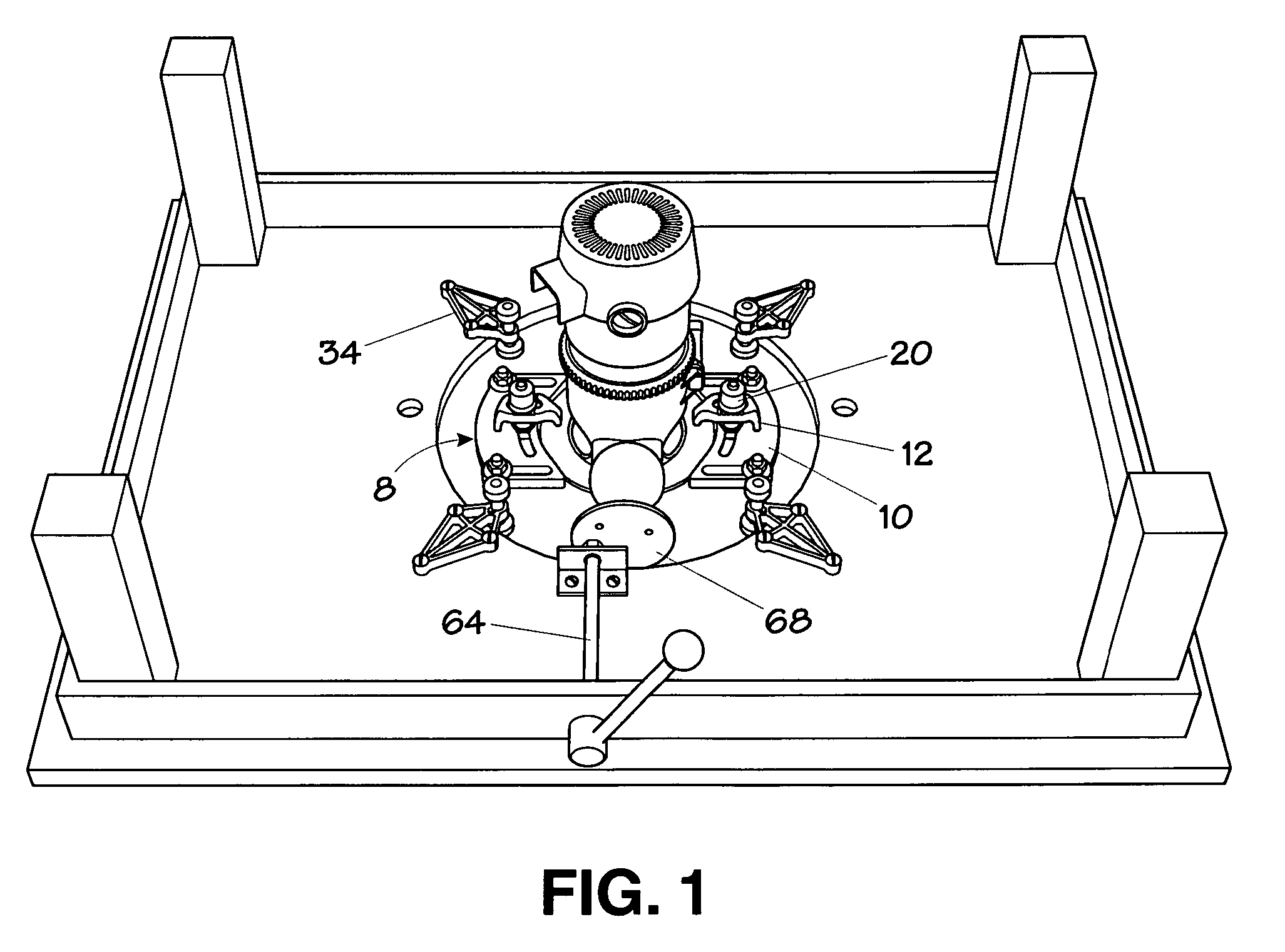
[0052]The components of the plate clamps 8 of this invention are shown assembled on the right side and exploded on the left side of FIG. 2. Each clamp 8 includes a clamp base 10 secured to the plate 14 and an arm 12 for securing the router (not shown in FIG. 2) to the plate 14. Washer 16, having one or more groove-engaging protrusions or tabs 15 (shown in FIGS. 4 and 5) engages at least one of the grooves 18 on arm 12 to prevent any risk that arm 12 will move after knurled nut 20 is tightened. FIG. 3 is a bottom view of the plate 14 and clamps 8. Tabs 15 are visible in both the side view of FIG. 4 and the top view of FIG. 5.

[0053]Arched clamping arm 12 rests against each clamp base 10 and against the router base (not visible in FIG. 2). Each end of the cl...


PUM


Abstract

A router table assembly including a plate with router mounting clamps, a plate leveling system for securing and positioning the plate in the router table and a plate lift assembly. Components of this system are usable separately. Use of these components together provides a particularly easy to use, highly functional router table apparatus.

Description

RELATED APPLICATION DATA[0001]This application claims priority to U.S. Application Ser. No. 60 / 604,536 filed Aug. 25, 2004, which is incorporated herein by this reference.FIELD OF THE INVENTION[0002]This invention relates to router tables generally and more specifically to router table plates, plate levelers, router to plate mounting structures and plate lifts.BACKGROUND OF THE INVENTION[0003]Because of their versatility, electric routers are very widely used in woodworking, particularly in home and small commercial shops. Such routers are generally intended to be used by moving the router relative to a stationary work piece with a portion of the router base bearing against the work piece.[0004]Using a router in this manner is suitable if the work piece is substantially larger than the router or is immovable. For smaller work pieces, such as the sizes used in trim work, furniture making or cabinetry, it is often more practical to invert the router such that the cutter is oriented ge...

Claims


Application Information

Patent Timeline
IPC IPC(8): B25H1/02
CPCB27C5/02B27C9/02B27C5/10
Inventor HYDE, BRENT K.
Owner LEE VALLEY TOOLS
Why Eureka
Try Eureka