

Connector device
- Summary
- Abstract
- Description
- Claims
- Application Information
AI Technical Summary
Benefits of technology
Problems solved by technology
Method used
Image

Examples
first embodiment
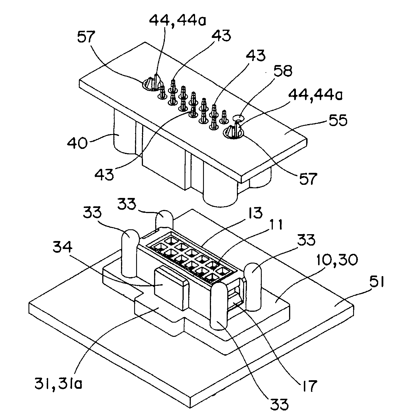
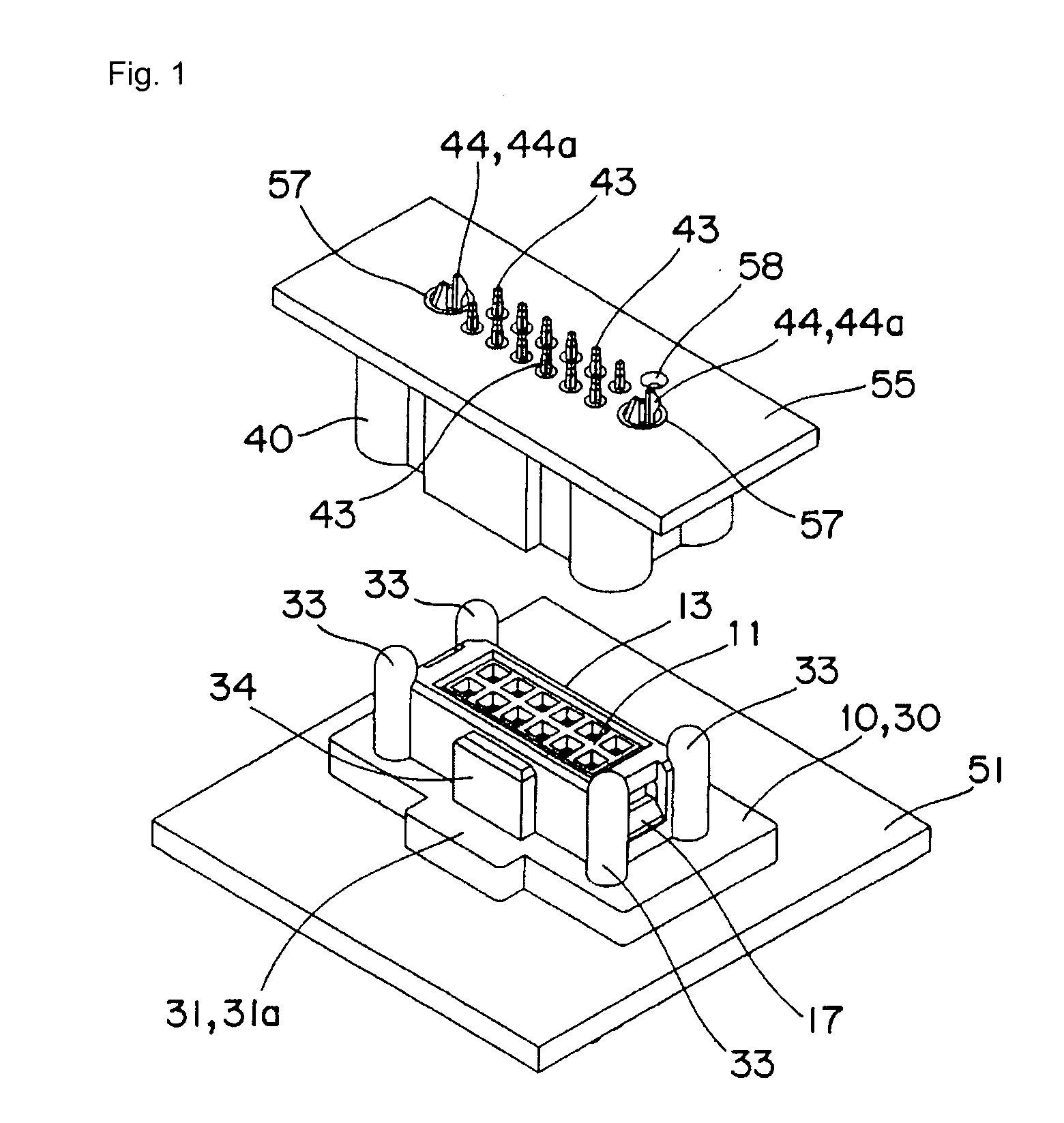
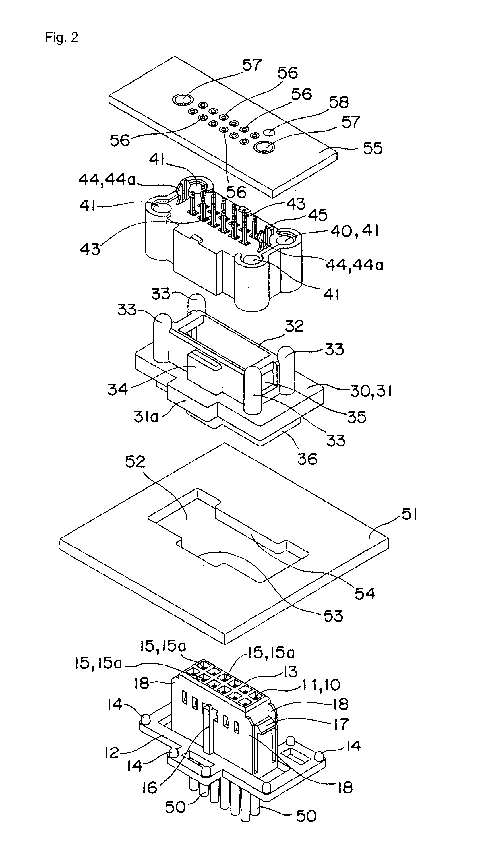
[0035]The connector device is configured by a socket 10 including a socket main body 11 and a socket cover 30, and a plug 40, as shown in FIGS. 1 and 2.
[0036]The socket main body 11 has a frame shaped collar part 12 integrally molded at the outer peripheral surface of a housing 13 having a solid rectangular shape that can be play-fitted to a fit-in hole 52 of an attachment substrate 51, to be hereinafter described, as shown in FIG. 3. A positioning projection 14 is arranged in a projecting manner at each corner of the frame shaped collar part 12. Two rows of pin holes 15 are formed at a predetermined pitch in the housing 13, and a connection pin 20, to be hereinafter described, is press fit from below into each pin hole 15 (FIG. 10). In particular, four-sided truncated pyramid guide concave parts 15a communicating to the pin holes 15 are formed at the upper end face of the housing 13. Furthermore, a guide rib 16 is arranged in a projecting manner at the side surface of the long sid...
fourth embodiment
[0052]The fourth embodiment shows a case where the connector device according to the previous embodiments is applied to electrical connection of the pinball game machine 60, as shown in FIG. 15.
[0053]In the pinball game machine 60 according to the present embodiment, the pinball game machine main body 61 is hinge supported at the machine frame 62, and the play board 63 is rotatably supported on the front surface side of the pinball game machine main body 61. Furthermore, a glass door frame 65 attached with a transparent glass 64 is hinge supported at the front side of the play board 63.
[0054]According to the present embodiment, the socket 10 is slidably attached to the attachment plate 61a of the front surface side of the pinball game machine main body 61, and the plug 40 is attached to the rear surface of the play board 63 by way of the print substrate 55. Thus, even if the assembly accuracy of the play board 63 with respect to the pinball game machine main body 61 is low, the plug...
fifth embodiment
[0055]The fifth embodiment shows a case where the connector device according to the previous embodiments is applied to a ball discharging unit 70 of the pinball game machine 60.
[0056]The ball discharging unit 70 arranged on the rear surface side of the pinball machine main body 61 has ball feeding tubular body 71 of one part thereof rotatably hinge supported with respect to the attachment plate 61b. The plug 40 is attached to the front surface side of the ball feeding tubular body 71 by way of the print substrate 55. The socket 10 is slidably attached to the attachment plate 61b arranged on the rear surface side of the pinball machine main body 61.
[0057]According to the present embodiment, the plug 40 is fitted into the socket 10 and electrically connected even if the attachment accuracy of the plug 40 with respect to the ball feeding tubular body 71 is low since the socket 10 is sled and position adjusted. Thus, similar to the fourth embodiment, even if the attachment accuracy is l...
PUM
 Abstract
Description
Claims
Application Information