Wire harness

Active Publication Date: 2017-05-04
SUMITOMO WIRING SYST LTD
View PDF0 Cites 0 Cited by
  • Summary
  • Abstract
  • Description
  • Claims
  • Application Information

AI Technical Summary

Benefits of technology

[0013]In this configuration, in the wire harness according to the present invention, in a state where the heat-shrinkable tube prior to heat shrinkage is held in the tubular hole of the holding tube portion on the connector side, the connection terminal fixed to the end portion of the covered electrical wire is passed through the heat-shrinkable tube and the connection portion of the connection terminal can be irremovably inserted in the terminal insertion hole of the connector. Thereafter, by applying heat from outside the holding tube portion, the heat-shrinkable tube can be caused to heat shrink and cover the area including the area from the lead wire end portion to the fixating portion of the connection terminal fixating the insulation sheath. In other words, when an operation of inserting the connection portion of the connection terminal into the terminal insertion hole is performed, a conventional operation of passing the covered electrical wire through the heat-shrinkable tube is performed simultaneously therewith. As a result, there is no need to separately perform the conventional operation of passing the covered electrical wire through the heat-shrinkable tube, thus enhancing assembly workability.
[0014]In addition, since the holding tube p

Problems solved by technology

Contact potential difference occurs in an area where dissimilar metals are in contact with each other, and when moisture acting as an electrolyte aqueous solution adheres to the contact area, corrosion may occur on the metal having a lower standard electrode potential.
For example, in a case where a copper connection terminal

Method used


Image

  • Wire harness
  • Wire harness
  • Wire harness

Examples


first embodiment

[0026]First, a first embodiment of the present invention is described with reference to FIGS. 1A and 1B through FIGS. 3A and 3B.

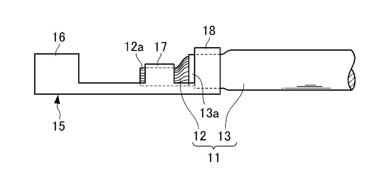
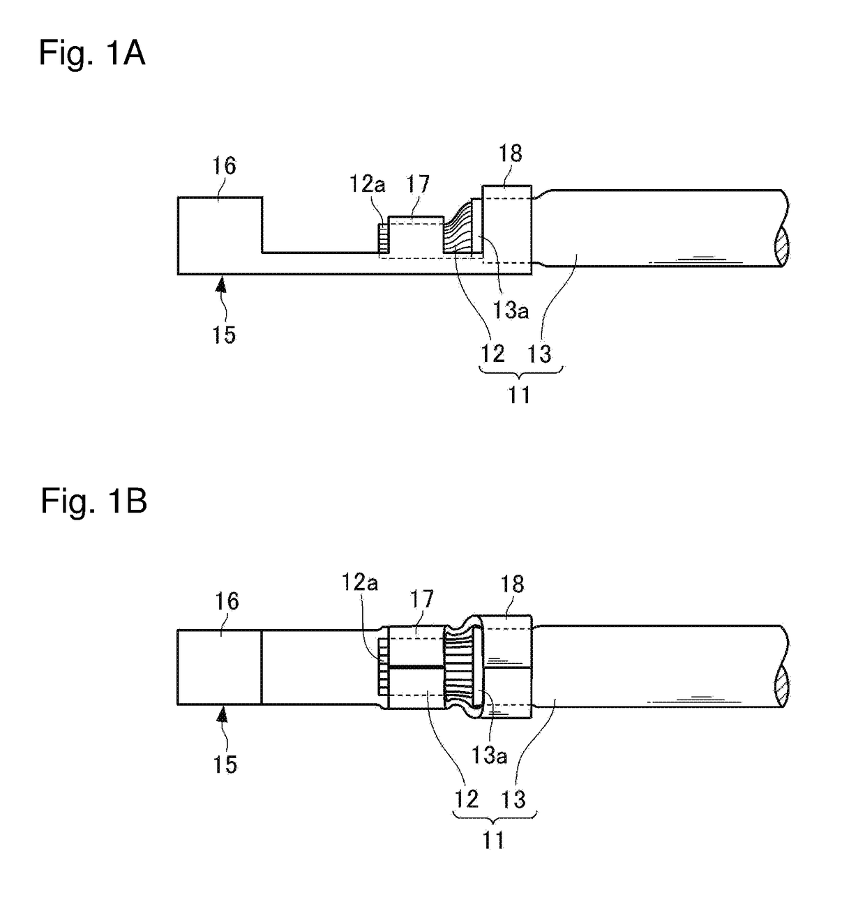
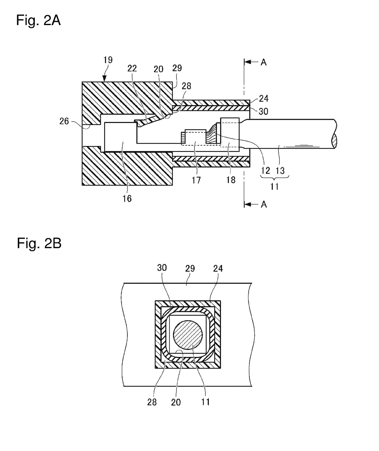
[0027]A wire harness 1 according to the first embodiment of the present invention includes a plurality of covered electrical wires 11 where an insulation sheath 13 is peeled off of each covered electrical wire 11 to expose a lead wire end portion 12a, a connection terminal 15 fixed to an end portion of each covered electrical wire 11, a heat-shrinkable tube 30 in a heat-shrunk state covering a predetermined area of the end portion of each covered electrical wire 11 that requires a waterproofing shield, and a connector 19.

[0028]As illustrated in FIGS. 1A and 1B, each covered electrical wire 11 includes a lead wire 12 having a bundle of aluminum wires having a small diameter and the insulation sheath 13 made of a PVC (polyvinyl chloride) material and the like that covers the lead wire 12, and has a configuration in which the end portion (a length of 10-15 mm,...

second embodiment

[0049]Next, a second embodiment of the present invention is described. FIGS. 4A and 4B illustrate a state in which the heat-shrinkable tube 30 prior to heat shrinkage is held in a holding tube portion 44 according to the second embodiment of the present invention. The second embodiment of the present invention differs from the first embodiment only in the cross-sectional shape of the holding tube portion 44. Therefore, other components are assigned reference numerals identical to those of the first embodiment and descriptions of the configuration, operation, and effects thereof are omitted.

[0050]As illustrated in FIG. 4B, the holding tube portion 44 has an elliptical cross-section. A tubular hole 45 of the holding tube portion 44 is larger than the terminal insertion hole 20 illustrated in FIG. 4B in a plan view. Thus, similar to the first embodiment of the present invention, the abutting surface portion 28 is formed in the step shape on a seam of the tubular hole 45 and the termina...


PUM


Abstract

A wire harness includes a plurality of covered electrical wires where an insulation sheath is peeled off of each covered electrical wire to expose a lead wire end portion, a connection terminal fixed to an end portion of the covered electrical wire, a heat-shrinkable tube having a hot-melt adhesive laminated to an inner surface thereof covering a predetermined area in a heat-shrunk state, and a connector that irremovably houses the connection terminal in each terminal insertion hole. A connection-side end surface of the connector that is on a side where the connection terminal is connected is positioned so as to conform to an end of the heat shrunk heat-shrinkable tube near a first barrel portion. The connector has a holding tube portion extending integrally from the connection-side end surface and that covers the heat shrunk heat-shrinkable tube, the holding tube portion having a tubular hole that holds the heat-shrinkable tube.

Description

CROSS-REFERENCE TO RELATED APPLICATIONS[0001]The present application claims priority under 35 U.S.C. §119 of Japanese Application No. 2015-212658, filed on Oct. 29, 2015, the disclosure of which is expressly incorporated by reference herein in its entirety.BACKGROUND OF THE INVENTION[0002]1. Field of the Invention[0003]The present invention relates to a wire harness having an electrical wire that has a connector provided to an end portion thereof.[0004]2. Description of Related Art[0005]Traditionally, in a wire harness having an electrical wire that has a connector provided to an end portion thereof, a structure is often employed where a connection terminal crimped to the end portion of the electrical wire is inserted and locked in a terminal insertion hole of the connector (see FIGS. 6A and 6B). In this structure, different types of metal may be used in a lead wire constituting the electrical wire, and the connection terminal. Contact potential difference occurs in an area where di...

Claims


Application Information

Patent Timeline
IPC IPC(8): H01R9/24H01B7/00H01R4/18H01R4/72
CPCH01R9/2416H01R4/185H01B7/0045H01R4/72H01R43/005H02G15/1806H01R13/5216
Inventor YAMAMOTO, MORICHIKA
Owner SUMITOMO WIRING SYST LTD
Why Eureka
Try Eureka