Motor Vehicle Steering Column

a steering column and motor vehicle technology, applied in the direction of steering parts, vehicle components, transportation and packaging, etc., can solve the problems of large adjustment of the deflecting clamp, and the length of the lever to be correspondingly extended. , to achieve the effect of precise height setting

Inactive Publication Date: 2011-09-08
DAIMLER AG
View PDF13 Cites 12 Cited by
  • Summary
  • Abstract
  • Description
  • Claims
  • Application Information

AI Technical Summary

Benefits of technology

[0010]The lever may be arranged mirror-symmetrically with respect to the longitudinal axis of the

Problems solved by technology

This arrangement has the drawback that, for relatively large adjustments, the lever length has to be correspondingly enlarged.
However, it is precisely in the cockpit region that the construction spac

Method used


Image

  • Motor Vehicle Steering Column
  • Motor Vehicle Steering Column
  • Motor Vehicle Steering Column

Examples


Embodiment Construction

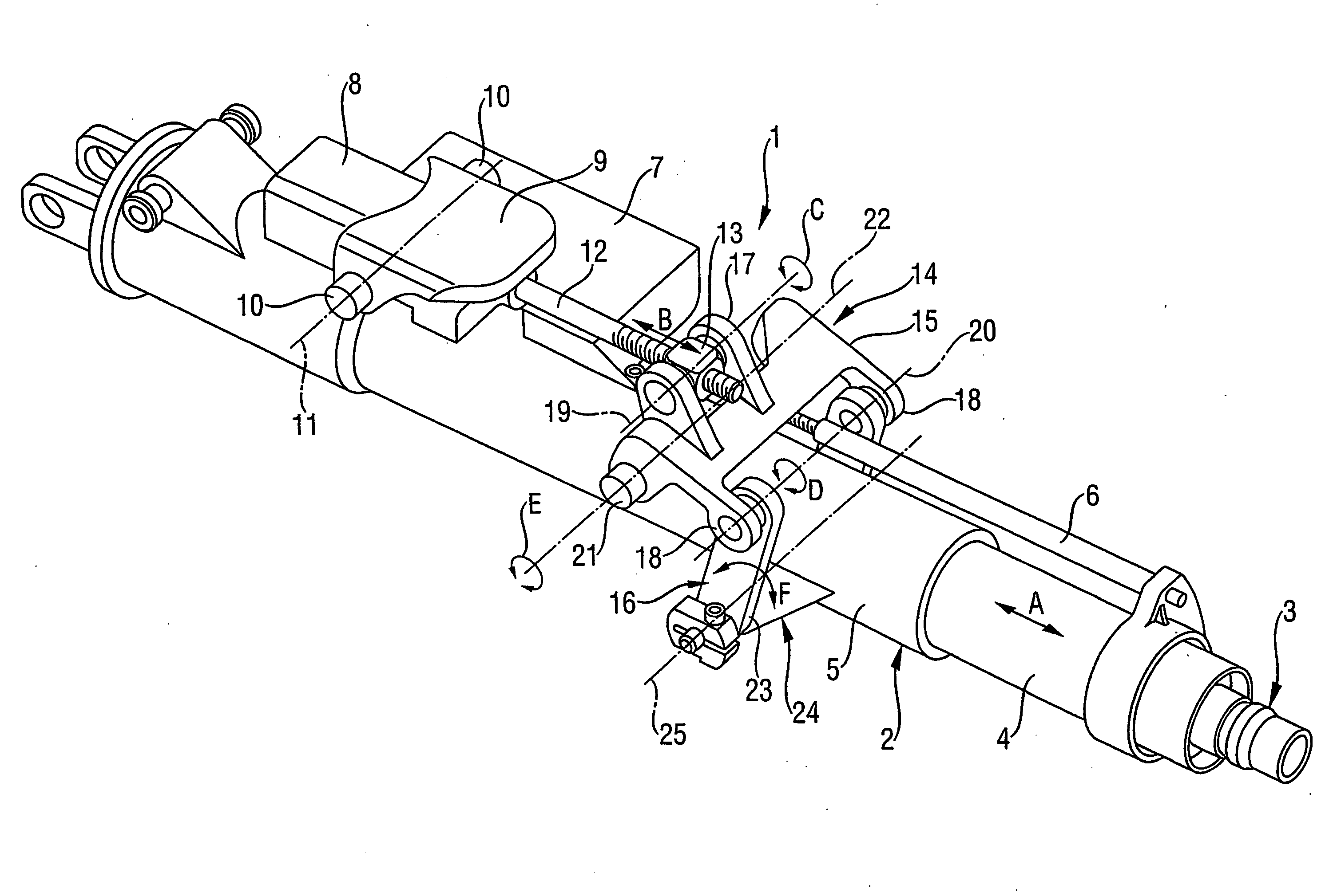
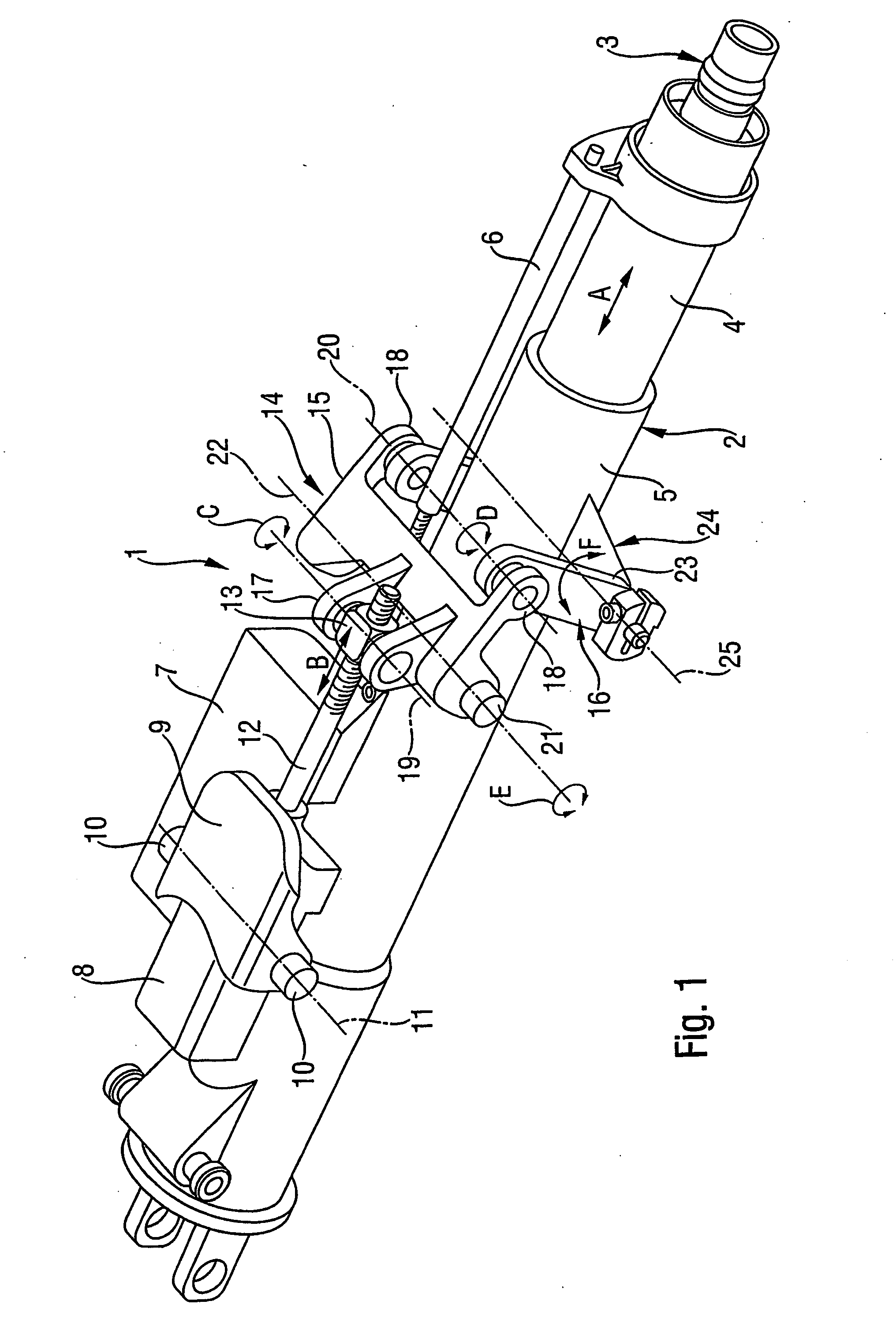
[0015]FIG. 1 illustrates a motor vehicle steering column 1 with a two-part, telescopic steering column tube 2, in which a steering spindle 3 is rotatably mounted. The steering column tube 2 is connected to a bracket which is fixed to the vehicle.

[0016]The steering column tube 2 includes an inner steering column tube section 4 and an outer steering column tube section 5. The inner steering column tube section 4 is connected to a threaded spindle 6 which is driven by an electric motor 7. Depending on the direction of rotation of the threaded spindle 6, the inner steering column tube section 4 is moved into or out of the outer steering column tube section 5 in accordance with the arrow direction A, so that the motor vehicle steering column 1 is set comfortably in the longitudinal direction.

[0017]A second electric motor 8 is fastened to a mount 9 on the outer steering column tube section 5. The outside of the mount 9 has two axle stubs 10 which together form a pivot axis 11. The axle st...


PUM


Abstract

A motor vehicle steering column includes a bracket fixed to the vehicle and a steering column tube. The steering column tube may be adjusted in inclination relative to the bracket fixed to the vehicle via an adjusting device. The adjusting device includes a lever which is mounted pivotably on the bracket and may be deflected about a pivot axis by a driving device. The motor vehicle steering column may permit a maximum inclination setting irrespective of the available construction space. A deflecting clamp which is connected pivotably to the steering column tube is coupled to an output end of the lever.

Description

FIELD OF THE INVENTION[0001]The present invention relates to a motor vehicle steering column with a bracket fixed to the vehicle and a steering column tube.BACKGROUND INFORMATION[0002]German Published Patent Application No. 196 41 152 describes a motor vehicle steering column, in which a steering column tube can be adjusted in inclination relative to a bracket fixed to the vehicle via an adjusting device. The adjusting device includes a lever which is mounted pivotably on the bracket and can be deflected about a pivot axis by a driving device—here an electric motor. The driving device drives a drive spindle on which a spindle nut is seated. The forward movement of the spindle nut causes the lever to be deflected on the bracket about a pivot axis, so that the steering column tube which is connected to the lever is carried along upward or downward.[0003]This arrangement has the drawback that, for relatively large adjustments, the lever length has to be correspondingly enlarged. Howeve...

Claims


Application Information

Patent Timeline
IPC IPC(8): B62D1/183B62D1/181B62D1/187
CPCB62D1/181
Inventor BORN, CHRISTIANKNOLL, KARL-HEINZMAUSOLF, KARSTENRAABE, HERMANNSCHULIERS, WOLFGANG
Owner DAIMLER AG
Why Eureka
Try Eureka