Independent front wheel suspension, vehicle equipped with such a front wheel suspension, and method of producing a sprung suspension

a front wheel suspension and independent technology, applied in the direction of steering linkages, electrical steering, transportation and packaging, etc., can solve the problems of limiting the possible ground clearance and the scope of positioning, and the solution is usually difficult to fit, etc., to achieve large lateral forces and large vertical adjustment

Inactive Publication Date: 2009-06-09
VOLVO TRUCK CORP
View PDF13 Cites 13 Cited by
  • Summary
  • Abstract
  • Description
  • Claims
  • Application Information

AI Technical Summary

Benefits of technology

[0008]An object of the present invention is to provide a compact wheel suspension that can absorb lateral forces of the vehicle while at the same time permitting a relatively large vertical adjustment of the wheel. According to the invention, this object is achieved by an arrangement for independent suspension of a wheel on a motor vehicle, especially front wheel suspensions for steered wheels. The invention is also applicable to double front axles and so-called pusher axles. The wheel suspension comprises (includes, but is not necessarily limited to) a stub axle connected to a stub axle carrier, a suspension arm which connects the stub axle carrier to the vehicle, and a stabilizer bar fitted transversely to the longitudinal axis of the vehicle. According to a preferred embodiment, the suspension arm is fixed against rotation relative to an outer end of the stabilizer bar and rotatably attached in at least one position axially separated from the outer end of the stabilizer bar. This embodiment counteracts the vertical sprung movement of the wheel.
[0013]The stabilizer bar is rotatably attached to the underside of the vehicle adjacent to the outer ends thereof, inside the attachment point of each of the suspension arms. In order to prevent flexure of the stabilizer bar when the suspension arms are subjected to lateral forces, a central section of the stabilizer bar may be rotatably attached to the underside of the vehicle at at least one attachment point. For an optimum distribution of the lateral forces imposed, the suspension arm may be rotatably attached to the stabilizer bar on either side of the attachment point. This embodiment also permits the absorption of large forces in the longitudinal direction of the vehicle, for example when braking.
[0016]The arrangement according to the invention has a pair of stub axles mounted on stub axle carriers on either side of the vehicle. In order to meet current statutory requirements, the stub axles must be mechanically connected to one another. This means that a steering gear provided with a pitman arm acts on one of the stub axles, the movement being transmitted to the other stub axle on the opposite side of the vehicle via a system of suspension links. According to one embodiment, the system of suspension links comprises a transverse suspension link, which runs centrally through the stabilizer bar. This obviates the need to locate any part of the system beneath the vehicle where it may be exposed to external actions, or to form passages in the longitudinal members, which is complicated and leads to cost increases.
[0019]A major advantage with the embodiments specified above is that they provide a very compact independent wheel suspension, which allows large lateral forces and braking forces to be transmitted, together with a relatively large vertical adjustment of the vehicle's ground clearance.

Problems solved by technology

Such solutions are usually difficult to fit because of the limited space available for their installation.
This presents particular problems in the case of front wheel suspensions in which the space is severely limited by the location of the engine between the longitudinal frames.
A further problem with current wheel suspensions is that they limit the possible ground clearance and the scope for locating the engine.
These requirements are difficult to achieve with current solutions that have sprung, rigid axles that extend under the frame and the engine.
The disadvantages with this solution are that it becomes complicated due to all the additional links needed to absorb longitudinal forces and to transmit steering movements, and that the sub-frame takes up a lot of space.
In addition, DE 4021096 demonstrates a relatively compact wheel suspension which affords good ground clearance, but this solution cannot be applied to steered front wheel suspensions and cannot absorb larger lateral forces.

Method used


Image

  • Independent front wheel suspension, vehicle equipped with such a front wheel suspension, and method of producing a sprung suspension
  • Independent front wheel suspension, vehicle equipped with such a front wheel suspension, and method of producing a sprung suspension
  • Independent front wheel suspension, vehicle equipped with such a front wheel suspension, and method of producing a sprung suspension

Examples


Embodiment Construction

[0027]Preferred embodiments will be described with reference to the figures which should be appreciated as being illustrative schematic drawings of examples of the invention, but which are otherwise not limiting to the scope of the invention.

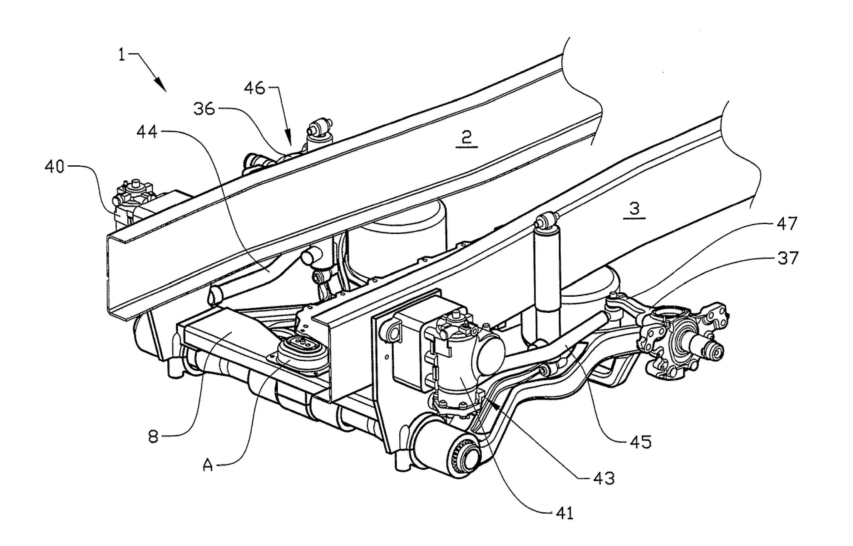
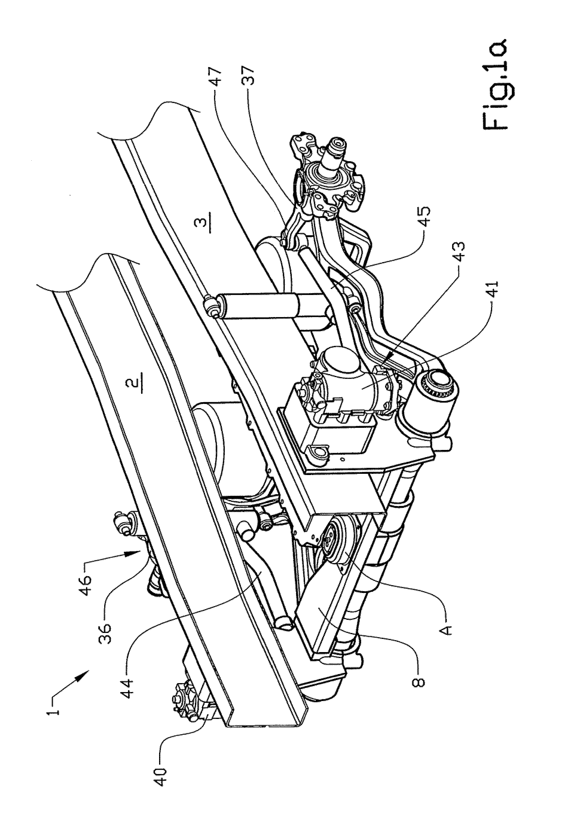
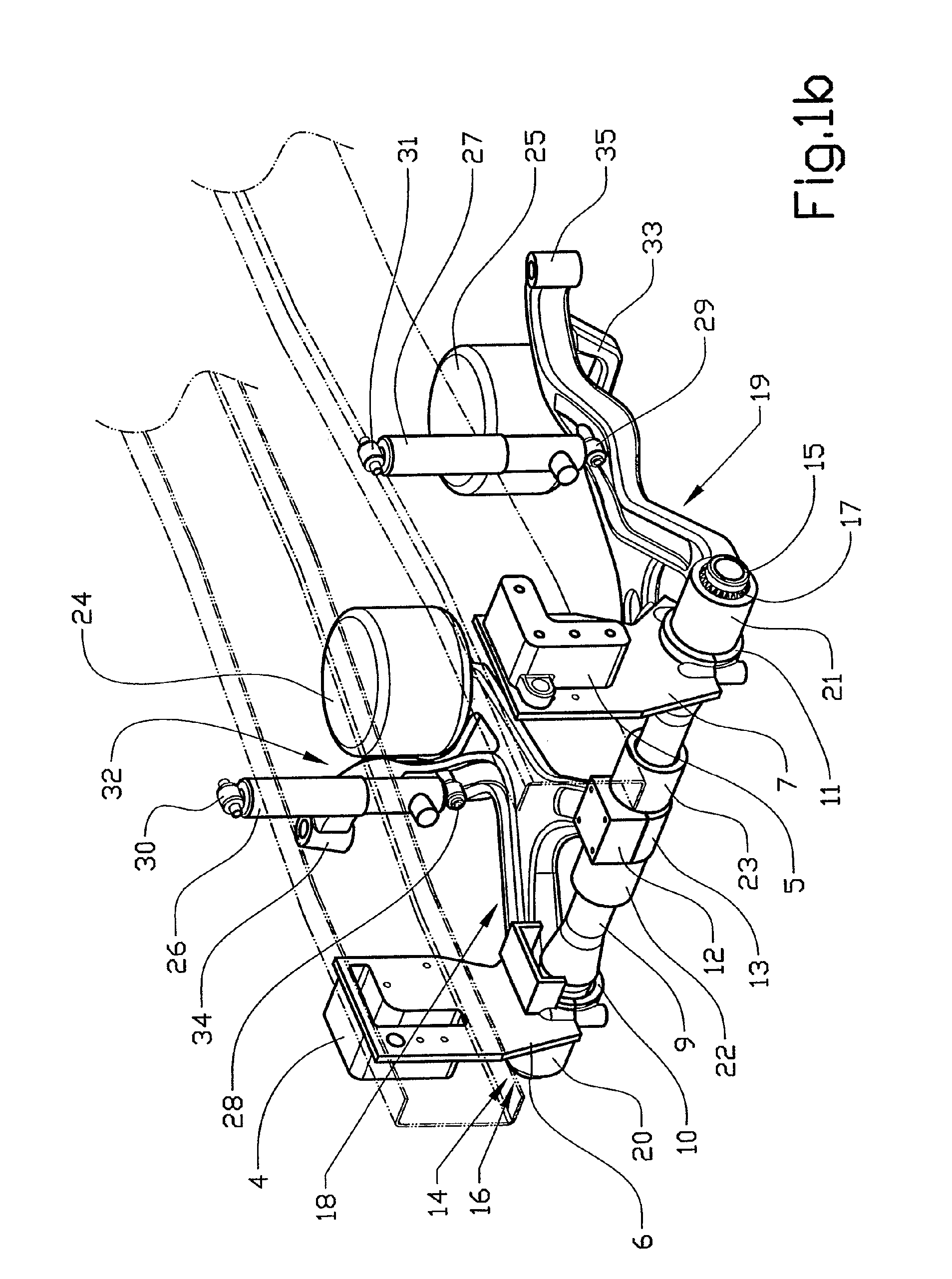
[0028]In the drawings, the invention is illustrated in intended applications on a vehicle frame typically taking the form of two longitudinal members of U or I-shaped cross-section, and where the engine is mounted between the members and the front wheels of the vehicle. Unless otherwise stated, in the following text, the design of the independent wheel suspension is described for one side of the vehicle.

[0029]FIGS. 1a and 1b show a front wheel suspension for a vehicle built on a frame 1, which comprises a pair of longitudinal members 2, 3. The members 2, 3 are indicated by dashed lines in FIG. 1b in order to expose the underlying components. On their front parts, the members have a pair of brackets 4, 5, which include respective plates 6, 7 that...


PUM


Abstract

Method and arrangement for providing a suspension for a wheel on a motor vehicle. The wheel suspension includes a stub axle (36, 37) connected to a stub axle carrier (34, 35), a suspension arm (18, 19) which connects the stub axle carrier to the vehicle, and a stabilizer bar (9) fixed transversely to the longitudinal axis of the vehicle. The suspension arm (18, 19) is fixed against rotation to an outer end (14, 15) of the stabilizer bar and rotatably attached in at least one position (22, 23) axially separated from the outer end of the stabilizer bar. The invention also relates to a vehicle provided with such an arrangement.

Description

CROSS-REFERENCE TO RELATED APPLICATIONS[0001]The present application is a continuation patent application of International Application No. PCT / SE03 / 00653 filed 30 Apr. 2003 which was published in English pursuant to Article 21(2) of the Patent Cooperation Treaty, and which claims priority to Swedish Application No. 0201728-3 filed 7 Jun. 2002. Said applications are expressly incorporated herein by reference in their entireties.TECHNICAL FIELD[0002]The invention relates to a wheel suspension for vehicles, in particular a steered independent front wheel suspension for heavy vehicles.BACKGROUND OF THE INVENTION[0003]Independent wheel suspensions, in particular front wheel suspensions, for vehicles built on a frame and that include a pair of longitudinal members of U- or I-shaped profile are most commonly of the McPherson-type, or comprise double suspension arms. Such solutions are usually difficult to fit because of the limited space available for their installation. This presents part...

Claims


Application Information

Patent Timeline
Patent Type & Authority Patents(United States)
IPC IPC(8): B60G3/12B60G3/14B60G9/04B60G7/00B60G7/02B60G11/26B60G11/64B60G13/08B60G13/10B60G21/055B62D5/04B62D5/06B62D6/00B62D7/08B62D7/20B62D101/00B62D113/00
CPCB60G3/145B60G7/02B60G11/64B60G21/055B62D7/20B60G2200/1322B60G2200/44B60G2202/135B60G2202/152B60G2204/143B60G2204/4302B60G2206/011B60G2206/427B60G2206/601B60G2206/602
Inventor LUNDMARK, ANDREAS
Owner VOLVO TRUCK CORP
Why Eureka
Try Eureka