
Structure of lead wire protective tube

A wire protection and tube structure technology, applied in the directions of linear motion shafts, flexible shafts, shafts, etc., can solve problems such as increased production of machines and tools, wire movement blocked, brittle cracks, etc., to save costs and stabilize the protection effect.

Inactive Publication Date: 2009-09-16
温芫鋐
View PDF1 Cites 1 Cited by
  • Summary
  • Abstract
  • Description
  • Claims
  • Application Information

AI Technical Summary

Problems solved by technology

[0005] The existing protection tube uses one port with a smaller diameter and the other port with a larger diameter. One end of the smaller diameter has an inclined tapered surface to socket the other protection tube with a larger diameter, so as to be connected in series to accommodate the wires. And the plastic elastic tube, because the brake wire is pulled by tension, so the wire is pulled and displaced in the protection tube, so the existing structure is to set a plastic elastic tube around the wire so that the protection tube and the wire do not directly contact, so as to avoid Affect the movement of the wire, so it is still necessary to install a plastic elastic tube, even if the protective tube can be bent according to the demand; but the plastic elastic tube is easy to be brittle in the protective tube after a long period of use, so that the brittle plastic elastic tube is embedded in the In the protective tube, it affects the protective effect of the protective tube, and makes the movement of the wire blocked
Moreover, the plastic elastic tube is made by covering the wire with plastic, which not only needs to increase the production equipment, but also increases the manufacturing cost; moreover, the existing structure uses a smaller diameter of one port and a larger diameter of the other port, thereby Sleeve-shaped protective tubes, but this structure only uses different caliber settings, which obviously cannot be firmly joined. If it is not tightly connected in series, it is easy to loosen and cannot achieve the coating effect

Method used


Image

  • Structure of lead wire protective tube
  • Structure of lead wire protective tube
  • Structure of lead wire protective tube

Examples


Embodiment Construction

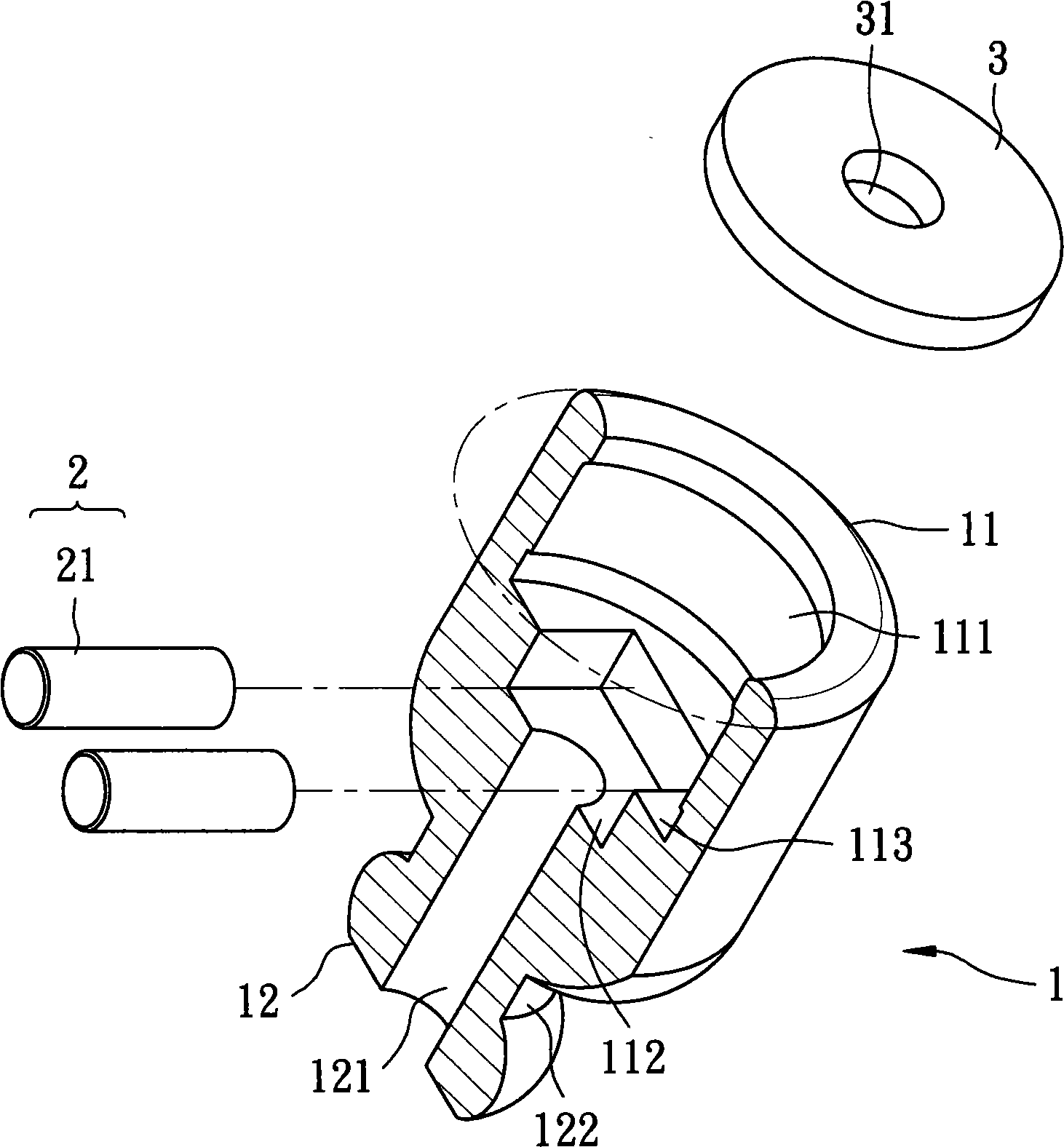
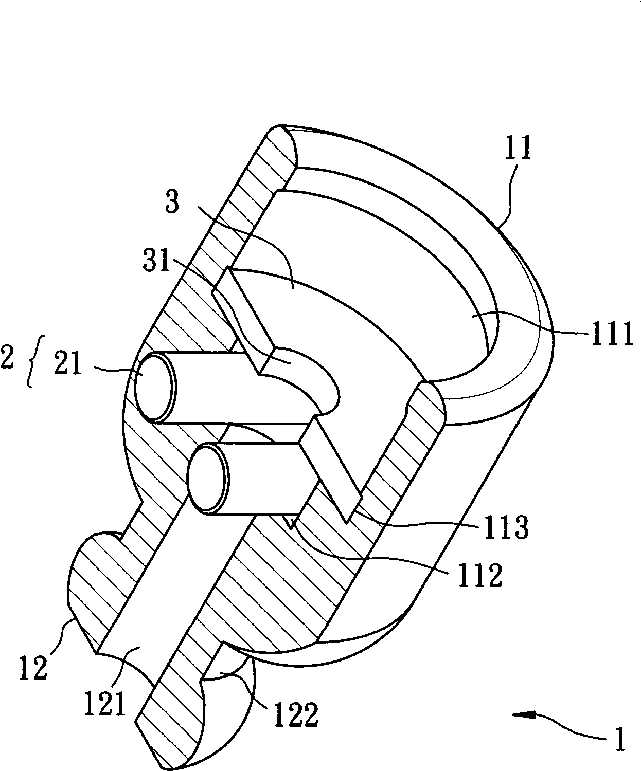
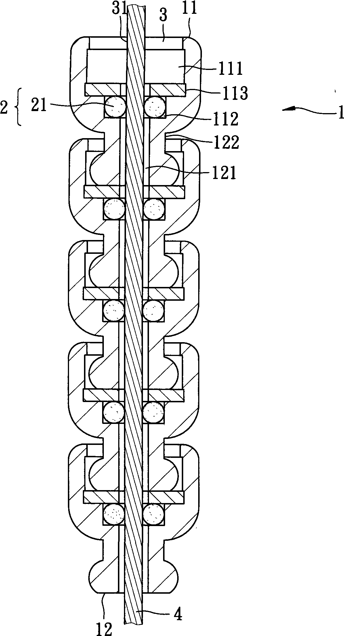
[0032] The present invention relates to a wire protection tube structure, please refer to Figure 1 to Figure 4 As shown in the first embodiment, it includes a shaft tube 1, the shaft tube 1 is provided with a first end 11 and a second end 12, wherein:

[0033] Such as figure 1 As shown, since the perspective view cannot show the structure installed inside the shaft tube 1, the part of the shaft tube 1 is shown in section, as shown in figure 2 shown;

[0034] The shape of the shaft tube 1 is generally columnar, the diameter of the first end 11 is larger than that of the second end 12, the shaft tube 1 is provided with a ring recess 122 adjacent to the second end 12, and the second end 12 The shape has a curved surface; the first end 11 of the shaft tube 1 is axially provided with a housing part 111, the diameter of the housing part 111 is slightly larger than or equal to the second end 12 of the shaft tube 1, and the inner bottom surface of the housing part 111 A slightly ...


PUM


Abstract

The invention provides a structure of a lead wire protective tube, which includes a shaft tube, the shaft tube is provided with a first end and a second end, wherein the diameter of the first end of the shaft tube is greater than that of the second end, the first end of the shaft tube is axially provided with a containing part, the inner bottom surface of the containing part is axially and concavely provided with a containing groove which is internally provided with at least two rolling bodies, the inner bottom surface of the containing groove is axially provided with a containing space in a penetrating way, the containing space penetrates to the second end from the containing part at the first end so that the first end and the second end of the shaft tube are communicated with each other, the distance from the rolling body to the neighboring body is less than the axial section diameter of the containing space; the bottom surface of the containing part near the containing groove is provided with a sealing cover, and the center of the sealing cover is provided with a through hole in the penetrating way; and with the structure, the lead wire can be protected by being arranged in the shaft tube and does not need to be coated with the plastic tube.

Description

technical field [0001] The invention relates to a bicycle wire protection tube, in particular to a wire protection tube structure which has a relatively large pivot angle, and the wire does not need to be coated with a plastic elastic tube, but can be directly installed inside. Background technique [0002] At present, with the advocacy of outdoor leisure activities, riding a bicycle is now a popular leisure activity, and the design of the vehicle is therefore constantly improving. Whether it is a sports competitive bicycle or a leisure and comfortable bicycle, there are Great progress, among them, the setting of the brake wire is a crucial part for riding a bicycle. In the past, the brake wire of the bicycle was directly exposed to the outside of the car body, resulting in wind, sun and rain, even if the brake wire is steel. Cable manufacturing will still be weathered and rusted, so the general industry is to wrap an elastic plastic skin on the outside of the brake wire. V...

Claims


Application Information

Patent Timeline
IPC IPC(8): F16C1/20F16C1/26
CPCF16C1/26
Inventor 温芫鋐
Owner 温芫鋐
Learn More